About Watch Movements
Copyright © David Boettcher 2005 - 2026 all rights reserved.This page is intended to convey some basic information about the movements of mechanical watches (sometimes called the “mechanism” or “works”, although watchmakers have never used these terms). It gives some basic terms for the parts of a movement so that you can ask questions about them more confidently.
If you want to know about how to care for a mechanical watch, including advice about what can go wrong and regular cleaning and oiling, see Looking After a Mechanical Watch.
If you have any questions or comments, please don't hesitate to contact me via my Contact Me page.
Lever Escapement Movement
Good quality watches and wristwatches usually had movements with lever escapements. The picture here of a movement with a lever escapement should help with some basic terms for the parts of a movement which you can see when you open the case back. If you click on it a larger version should open in a pop-up window where you can see more detail. If your movement doesn't have the escape wheel pivot visible like this one it might have a cylinder escapement, see cylinder escapement further down this page.
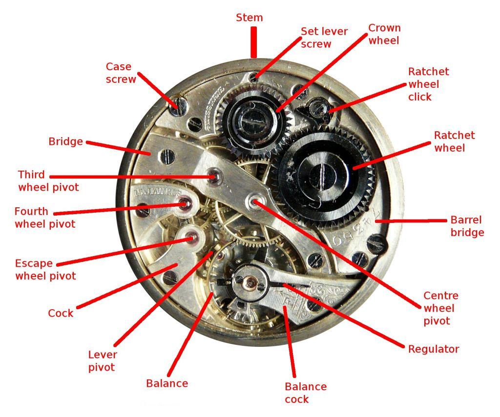
Lever escapement movement - click to enlarge
I have indicated where the winding stem enters the movement at the top of the picture. The stem carries a pinion which meshes with the crown wheel. When the stem is turned, the pinion turns the crown wheel, which turns the ratchet wheel connected to the mainspring arbor, winding the spring that makes the watch go. The spring is contained within a barrel underneath the ratchet wheel.
The mainspring barrel has a gear on its outside which drives the pinion of the centre wheel directly, this is called a going barrel. The centre wheel turns once per hour and its arbor is extended through the bottom plate and turns the minute hand, and it also turns the hour hand through a 12:1 reduction gearing called the motion work. Every time the minute hand makes one revolution the hour hand makes 1/12 of a revolution, so one complete revolution of the hour hand takes 12 hours.
The centre wheel drives the pinion of the third wheel, and the third wheel drives the pinion of the fourth wheel, the speed of rotation increasing each time. The fourth wheel is usually arranged to make one turn every minute. Its pivot in the bottom plate is often extended so that it passes through the dial where it turns a seconds hand. Watches with the "traditional" layout of the one shown here rarely have centre seconds hands - see below for more details of watches with centre seconds dials.
The fourth wheel also drives the pinion of the escape wheel. In a lever escapement movement like the one pictured, the escape wheel is locked by a lever pallet, which you should just about be able to see if you click on the picture to get the larger version. The pallets are either side of the lever pivot which I have labelled, they are tiny pale ruby coloured things, one is just visible above the screw on the rim of the balance.
The balance and its spring form the oscillator that controls the timekeeping of the watch. The balance has a central arm that is mounted in the balance staff and carries a circular rim that is the oscillating mass. The balance spring is mounted above the balance. It is secured to the balance cock at its outer end by the stud. Its inner end is secured to the balance staff by the collet. The balance spring tries to hold the balance in one central position. If the balance is moved from that central position in either direction, the spring pulls it back. Like all masses on springs, the balance swings through the central position to the other side, and the spring then pulls it back from there.
As the balance swings back and forth, a small pin called the impulse pin or impulse jewel knocks the lever from one side to the other. Each time this happens, whichever pallet is currently locking the escape wheel releases and allows one tooth of the escape wheel to escape. The other pallet then catches the escape wheel and locks it, so that each time the balance swings, the escape wheel advances one tooth. Immediately after the locking pallet has released a tooth of the escape wheel, the escape wheel gives the pallet a push, which in turn makes the lever give a push to the balance through the impulse pin. This little push, or impulse as it is called, is what keeps the balance swinging backwards and forwards.
Once the balance has knocked the lever it carries on turning as far as its momentum and the little extra push it received from unlocking the escape wheel will take it against the resistance of the balance spring. When the balance has run out of energy it stops and then the balance spring accelerates it in the reverse direction. In passing it knocks the lever back the other way, and the sequence starts all over again.
The balance is so called because in early clocks there was no circular rim. The balance was a single central bar or arm with weights hanging from it to provide the mass. These weights were moved to control the time keeping, and the whole thing looked like a weighing balance and hence the name. Some people call the balance a "balance wheel" but this is incorrect. In watch work, wheels have teeth on their rims which engage with pinions. The balance does not have teeth on its rim and so it is not a wheel. Britten's Watch and clockmaker's handbook, dictionary and guide 14th ed, 1938, makes it clear that balance wheel was the wheel next to the balance in a verge clock, i.e. it was an alternative term for the escape wheel.
Watch Plates
The foundation of a watch is the bottom plate, also called the dial plate or pillar plate. This is the plate behind the dial that the barrel, fusee (if there is one), train and escapement sits on when the watch is dismantled.
The top plate is the plate above the train. This may be a full plate, ¾ plate, ½ plate, or individual cocks and bridges, also called a “bar movement”.
Full plate watch movements have two full, round, plates, and everything except for the balance and its cock sits between these. The balance, balance spring and balance cock are mounted on top of the top plate.
To make movements thinner, part of the top plate was cut away so that the balance could be brought in between the two plates with its cock mounted on the bottom plate. These movements are classified by how many bearings remain in the large plate.
In a three-quarter plate movement, the top plate carries the pivots of the barrel, centre, third, fourth and escape wheels. The plate is cut away for the balance, which has a separate cock mounted on the bottom plate so that the top of the cock is level with the top plate.
In a half plate movement, the escape wheel is also pivoted in a separate cock mounted on the bottom plate. The top plate carries the pivots of the barrel, centre, third and fourth wheels.
Movements where bridges and cocks are used instead of a top plate, are called “Geneva” or “bar” movements.
A bridge has a support and screw at each end, a cock has just one support and screw, so it is a cantilever and must be short to be sufficiently rigid.
Rollers
In a lever escapement, the roller is a boss or collet mounted on the balance staff. It carries the impulse pin, which moves the lever to unlock the escape wheel and then receives an impulse from the lever. It also functions as a safety device to prevent the lever from unlocking at the wrong point in the cycle if the movement receives a knock.
A notch in the roller allows a guard pin mounted on the lever to pass only during the action of unlocking an impulse. At other times, if the watch is subjected to a shock, the guard pin hits the edge of the roller which prevents the lever from moving out of place.
A double roller lever escapement has separate impulse and safety rollers, the safety roller being made smaller to reduce friction when the guard pin hits it, which reduces the effect of a shock on timekeeping. Older lever escapements had a single roller.
Assortiments
In the Swiss watch industry, escape wheels, levers and rollers were made by single manufacturers as a combination called the ‘assortiment’. The reason for this is that the relationship between the geometry of the teeth of the escape wheel, the lever and the impulse jewel on the roller is critical to the functioning of the escapement, so these parts were made together by a specialised assortiment manufacturer and supplied as carefully matched sets to ébauche manufacturers.
The oldest assortiments factory in Le Locle was founded in 1850. On 26 February 1883, the first official record of this business read ‘The head of the Charles Louis Huguenin business in Le Locle is Charles Louis Huguenin, from Le Locle and domiciled there. Type of business: Anchor assortiment factory. Offices: Progrès, 59.’ Charles Louis died in January 1885 and the business was taken over by his widow Sophie under the name ‘veuve de Chs Ls Huguenin’ (window of Chs Ls Huguenin).
In 1892, the business under the name ‘veuve de Chs Ls Huguenin’ was transferred to Sophie's two sons, Charles-Adolphe and Louis Huguenin-Virchaux, who established a general partnership in Le Locle on April 23, 1892, under the name Charles-Louis Huguenin. This business took over the assets and liabilities of the former business of the widow of Charles-Louis Huguenin. Type of business: Anchor assortiment manufacturing. Offices: 59 and 60, Quartier Neuf.
In January 1917, the company passed to a new company ‘Chs et Ls Huguenin.’ Charles-Louis Huguenin, son of Charles-Louis, of Le Locle, and his two sons, Louis-Edouard and Charles-William Huguenin, all three manufacturers of assortments, residing in Le Locle, established under the corporate name Chs et Ls Huguenin, a general partnership company which commenced on 1 November 1917. Assortment factory; Rue de la Coneorde, No. 29.
This company became Assortiments la Concorde, which was incorporated in 1928. In 1932, this factory and others, including Assortiments Stella, were combined as the Fabriques d'Assortiments Reunies (FAR). In 1984, FAR merged with Nivarox SA to become Nivarox-FAR SA, specializing in the production of oscillating and escapement components for mechanical watch movements.
Back to the top of the page.
Regulators
Now on a separate page at Watch Regulators.
Back to the top of the page.
Decoration
The plates, bridges and cocks of movements, and watch cases and metal dials, are often embellished with decorative patterns.
- Perlage: a form of engine turning produced by pressing the end of a rotating wooden peg charged with abrasive powder lowered repeatedly onto the surface to form a pattern of overlapping circles. These are sometimes described as looking like pearls, hence the name, or fish scales if there is more overlap.
- Damascening: individual straight or wavy lines in a repeated pattern. Damascening (pronounced with a soft "c" like "damaseen") originates in the technique used by sword smiths of Damascus of repeated forging and folding metal into many layers, like mille-feuille pastry, to produce sword blades of legendary toughness, which produces intricate banded patterns on the surface of the finished blade. This was principally used by American manufacturers and in America is called damaskeening. It was done either by hand or machine, and in the highest grade of America watches was very elaborate. Decoration such as damascening was particularly important to American manufacturers because movements and cases were selected separately at the point of sale; a movement needed to catch the customers eye.
- Côtes de Genè (Geneva Stripes): a series of parallel patterns across the plates and bridges of a movement made by a rotating tool in a vertical milling machine. Like Perlage, but with the tool dragged across the work to form strips rather than dotted repeatedly onto the surface.
- Guilloché: a fine geometric pattern cut into metal using a machine called a rose engine lathe. This is often seen on dials and cases, especially the dials of ladies' watch and the backs of pocket watch cases, but not on movements.
Back to the top of the page.
Watch Jewels
Now on a separate page at Watch Jewels.
Back to the top of the page.
Shock Protection
The pivots of the balance staff of a watch are made very thin to minimise friction, and are therefore delicate. If a watch is dropped or knocked, the shock can cause the balance staff pivots to bend, or more usually to break because they are very hard and brittle, causing the watch to stop or run inaccurately. Pocket watches and early wristwatches were both subject to this problem. It was not so much of a problem for pocket watches, which were normally kept in a pocket and only received a shock if accidentally dropped, but wristwatches are in a vulnerable position at the end of the arm, where they are very prone to getting knocked. Broken balance staff pivots were a common occurrence in early wristwatches and every watch repairer kept extensive stocks of spare balance staffs. Today the situation is different: broken balance staffs are rare and most watch repairers cannot or will not replace a balance staff.

Wilderness Catalogue 1931 Shock Absorber

Balance Assembly - Balance Staff in Green
The picture here shows a cross section through the balance assembly of a watch. The gold coloured item is the balance, the thing you see oscillating backwards and forwards as the watch runs. The green coloured item is the shaft on which the balance turns, called the "balance staff". The red items are four "jewels" that provide hard and low friction surfaces for the staff to turn on. The two jewels that the pivots of the staff pass through are called jewel bearings or "jewel holes", and the two that the ends of the staff bear on are called "end stones" or "cap jewels". The pivots of the balance staff, the reduced diameter portions at the ends, are made very small in diameter, just a few hundredths of a millimetre, in order to minimise friction, and are hardened to minimise wear. They are therefore very delicate and dropping a watch or knocking it against a hard surface can cause them to break.
Broken balance staff pivots were a common occurrence in early wristwatches, and every watch repairer kept a stock of spare balance staffs. Expert watch repairers could also make a new balance staff on a lathe if necessary. Turning a round shaft on a lathe is not a difficult job in principle, but the very small size of balance staff, especially of a wristwatch, which is just a few millimetres long and with pivots only a few hundredths of a millimetre in diameter, makes turning a balance staff challenging.
To overcome the problem of broken balance staff pivots, shock protection systems were devised with the idea of isolating the pivots from shocks that affect the watch. In around 1790 Abraham Louis Breguet invented what was probably the first system, which he called the "parachute" or "suspension élastique". The endstones of the balance staff were held in place by spring blades so that they move in the event of a shock, cushioning the balance staff pivots. Breguet presented the definitive version of his design at the French national industrial exhibition of 1806.
Other shock protection systems followed over the years. The image here is from "The Wilderness Catalogue" of Robert Pringle & Sons from January 1931 and shows a shock absorber movement fitted to a number of watches in the catalogue. The movement was made by the General Watch Co. under the brand Helvetia. The shock protection shown in the image was granted a Swiss patent on 31 October 1930, patent No. CH143073, priority date 24 September 1929.
Today, when every modern mechanical watch has shock protection, it seems surprising that it took so long for shock protection to be adopted. The reasons for this, and the eventual universal adoption of shock protection, are an interesting story in their own right which I discuss in the section below called "slow adoption".
Incabloc
The best known and most widely used shock protection system was and still is Incabloc, invented by Fritz Marti.
Marti was a Swiss engineer working at Fabrique Election of La Chaux-de-Fonds, owned by Georges Braunschweig. Well aware of the weakness of balance staff pivots he determined to do something about it. In April 1928 he created a watch fitted with a shock absorbing system that used movable balance staff jewels to protect the balance staff pivots from shocks. This design was granted Swiss patent CH 141098, filed 27 July 1929 and registered 15 July 1930. In 1931 Georges Braunschweig and Fritz Marti established Porte-Echappement Universel SA, now better known as Portescap SA, the name it adopted in 1963.
At Porte-Echappement, Marti continued his work and on 2 March 1933 filed an application for a new patent for a simplified spring cushioned bearing system, which was granted as Swiss patent CH 168494 on 15 April 1934. Previous systems used two separate springs, one for lateral and the other for axial shocks. Marti's new design incorporated a cone shape for the bearing housing that redirected lateral shock in an axial direction, thus requiring only one spring. Production started in June 1933 and the Incabloc trademark was registered by the company in Switzerland on 6 July 1933.
All shock protection systems work in basically the same way. The balance staff jewel bearings are held in place by light springs instead of being mounted rigidly in the plates. When a shock occurs the springs allow the jewels and pivots to move slightly, and a stronger part of the balance staff contacts a fixed part of the housing to take the shock. Once the shock is is over the springs return the jewels and pivots to their correct positions.

Incabloc Advert 1953
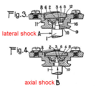
Incabloc patent CH 168494
The figure from the patent reproduced here shows this in action. In Fig 3 the balance staff has received a lateral impulse shown by arrow A. The staff pivot and its jewel bearing have mode to the right in the housing, and the cone shape of the jewel setting has caused it to ride up in the housing, lifting the cap jewel 5 against the spring 6. The stronger part of the balance staff 9 has contacted the housing to absorb the shock. In Fig 4 the balance staff has received an axial impulse shown by arrow B. In this case the jewel bearing and cap jewel have both been lifted vertically against the spring and the shoulder of the balance staff 10 has contacted the housing to absorb the shock.
The second figure reproduced here is from an Incabloc advert in 1953. It illustrates well all the components of the fully developed Incabloc design, including the famous “ lyre shaped spring”. This is the earliest advertisement mentioning the lyre shaped spring that I have found.
In the figure from the original patent, the spring labelled 6 which holds the cap jewel in place is shown fixed to the outer housing by a screw. Some time later, Incabloc engineers realised that they could make the spring clip into the housing and designed the lyre shaped spring, named after the musical instrument of similar shape. When looking at a watch with the fully developed form of Incabloc shock protection, the lyre shaped spring is clearly visible on the balance cock and its unique shape is a sure and easy way to identify an Incabloc shock proof setting.
The “T” shaped projection of the Lyre shaped spring clips into a slot in the housing and forms a type of hinge. The two opposite ends are sprung into a slot on the opposite side of the housing to retain the cap jewel and bushing in place. This makes it very quick and easy to service an Incabloc setting. Tweezers are used to spring the ends of the Lyre shaped spring out of place. The spring then hinges up and the cap jewel and bushing can be lifted out. This makes servicing an Incabloc setting much quicker than a traditional setting where the end stones are held in place with screws, oversoming one of the initial objections to shock proof settings.
Two of the first companies to adopt Incabloc were The West End Watch Co. in 1934 for their Sowar Prima, which became West End's most successful model, and Mido in 1935 for the Mido Multifort, became the best selling Mido watch until the 1950s. Both companies were also early adopters of the Taubert / Borgel company's waterproof Decagonal case.
Slow Adoption
Incabloc provided a real and commercial solution to the problem of broken balance staff pivots, but it wasn't immediately widely adopted. In fact, Incabloc was only one of many shock protection systems that had been developed since Breguet invented his "parachute" in 1790, but for some reason watch manufacturers were reluctant to incorporate these into their designs. The reasons for this, and the eventual universal adoption of shock protection, are an interesting story in their own right.
Shock protection for the balance staff pivots added extra cost, and most manufacturers were very cost sensitive, knowing that a higher price point would cost sales. There was also no demand at the time from the public for shock protection; everyone knew that watches were delicate and that if you dropped them they were liable to break, every watch repairer at the time was very well used to replacing balance staffs, and spare balance staffs were readily available from the manufacturers.

Incabloc advert September 1935
It might be thought that the military would be the first to require that shock protection be fitted. A watch with broken balance staff pivots is useless, and if that happened in the middle of a military manoeuvre it could be dashed inconvenient. One would think that army types would be breaking balance staffs left right and centre, but in fact the military were among the most reluctant to see watches fitted with shock protection.
The British "Army Trade Pattern" A.T.P and "General Services Trade Pattern" G.S.T.P. specifications emerged after the First World War and governed all British Army watches used before and during World War II, until they were superseded by the British War Office Specification No. R.S./Prov/4373A "Watch, Wristlet, Waterproof" or "W.W.W" specification in 1945. Neither the A.T.P, G.S.T.P. or the original 1945 version of the W.W.W. specification required shock protection, even though by the time of the W.W.W. specification shock protection of various forms had been commercially available for many years.
It is clear from this that breakage of balance staffs was not a great inconvenience to the British military. In fact, there was a dispute in the military committee that drew up the W.W.W specification about whether the benefit in reduction broken balance staffs result from shock protection would be offset by the increased time required for regular service of watches with shock proof settings, estimated at 10 - 15 minutes per watch. This was overcome by changes to the Incabloc design, the introduction of the clip in Lyre shaped spring, which made it quicker and easier to service a shock resistant setting than an old style setting with end stones held in place by screws. Nevertheless, it was not until 1947 that an amendment to the W.W.W. specification introduced a requirement for shock protection.
The conclusion must be that the general public and the military types who actually needed a wristwatch to perform their duties (mainly officers, not squaddies who were jumping in and out of trenches etc.) took care of them and that broken balance staffs were relatively rare. Before the second world war, vigorous pursuits such as trekking, diving and mountain climbing were the realm of a few and not followed as widely as they are today. If people outside the watchmaking profession even realised that shock protection was possible, they probably didn't think that they needed it.
The Power of Advertising
Shock protection was initially more widely advertised in America than in Europe. It seems that in America, with its more developed advertising industry, shock protection was used as an extra selling point or feature that could be used in advertising, persuading consumers that they needed it and to pay more for a watch with shock protection. Once watches that were "shock proof" entered the public's consciousness, the early adopters of such watches acquired "bragging rights", and any watch that didn't have shock protection was deemed old fashioned.
The feature that made Incabloc a commercial success, and the system that within a short period dominated the market for shock proof settings, was that it was a very clever modular design, making it easy for manufacturers to add to their movements, and it also speeded up watch servicing.
All balance staffs had, and still have, the same four jewels; two bearing or "jewel holes", and two "end stones" or "cap jewels". These all need to be cleaned when the watch is serviced, which means removing the cap jewels. In a watch without shock protection the cap jewels are held in place by one or two small screws, and the first shock protection systems used screws to hold the shock absorbing spring in place. Incabloc's breakthrough idea was to hold the cap jewel in place with the, now instantly recognisable, shaped Lyre shaped spring clip, which was also the spring that allowed the jewel to move when a shock occurred. Instead of taking longer to service than a setting without shock protection, Incabloc was faster, because instead of fiddling about with tiny screws, simply releasing the Incabloc spring, which was cleverly also held captive to the setting, allows the cap jewel to be removed, and then quickly clipped back into place after cleaning and oiling. This additional benefit was soon recognised and Incabloc came to dominate the market for shock proof settings.
The lifetime of Swiss patents in the 1920s and 1930s was normally 15 years, so Marti's patent for the original Incabloc system would have expired in 1949. After that many other shock protection systems such as Kif followed.
Downsides?
Shock protection is a real benefit, and today owners don't have to treat their watches as if they are delicate. A modern mechanical watch can be bashed about with gusto, and some owners take pride in wearing a watch that shows scars from trekking, mountaineering or diving. The only downside is for collectors of watches that were made before shock protection was widely used. The days of the local watch repairer who could replace a balance staff are now long gone, and watch repairers who can do this are few and far between, which makes replacing a staff with broken pivots an expensive operation. So if you have a watch without shock protection, take care of it!
Back to the top of the page.
Keyless Work
This section now has its own page at Keyless Work
Back to the top of the page.
Centre Seconds
Centre seconds refers to a watch where the seconds hand is pivoted in the centre of the dial at the same point as the hour and minute hands. There are two ways to achieve this, depending on how the movement is laid out. If the movement is laid out such that the fourth wheel is off centre, which would usually be used for a small seconds display at 6 o'clock, an extra wheel is mounted on an extended third wheel arbor, which drives the pinion of the centre seconds hand. This is called indirect centre seconds. Alternatively, the movement can be laid out such that the fourth wheel is at the centre of the movement instead of the second wheel. This is called direct centre seconds.
Indirect Centre Seconds

Indirect Centre Seconds: Click image to enlarge
When a centre second hand is fitted to a movement with the traditional layout, it is done by extending the arbor of the third wheel through the central bridge and mounting a wheel on the end of this extended arbor. The wheel drives a pinion on a central arbor which carries the seconds hand. Because the usual way of displaying seconds is to mount the seconds hand on the fourth wheel arbor, which rotates once a minute and therefore shows seconds directly, this alternative arrangement is called indirect, hence “indirect centre seconds”.
The large wheel and small pinion causes the rate of rotation of the seconds hand to be geared up from the slower rotation of the third wheel. From a pure engineering point of view, it would have have been better to take the drive from the fourth wheel, using two wheels of the same size providing a 1 : 1 ratio. However, that would result in the seconds hand turning anticlockwise, that is backwards from the usual direction.
The indirect seconds pinion is not part of the train of wheels carrying power from the mainspring to the escapement. The wheels in the train are kept in lock step by the force of the mainspring passing from wheel to wheel. Although the wheel train appears to move smoothly, it actually stops and starts on every tick, and the large ratio between the wheel and centre seconds arbor exaggerates this. Because the centre seconds arbor is not driving anything, it can flutter backwards and forwards each time it gets a kick from the third wheel due to play or backlash between the wheel teeth and the pinion leaves.
The picture here shows the large wheel mounted on the third wheel arbor above the centre bridge. The pinion on the centre seconds arbor is almost completely covered by the end plate of a flat spring. The purpose of the spring is to both hold the centre seconds arbor in place and, at the same time, create some friction to dampen down fluttering of the seconds hand.
Direct Centre Seconds
Fluttering of the seconds hand can be eliminated by rearranging the layout of the gear train to place the fourth wheel at the centre of the movement. This was common in nineteenth century English centre second chronograph watches, but not in Swiss watches before the twentieth century.
The fourth wheel rotates once a minute and therefore in this layout it drives the centre seconds hand directly. Because the fourth wheel is part of the train of wheels carrying power from the mainspring to the escapement it is kept in lock step by the force of the mainspring passing from wheel to wheel.
In this arrangement, the arbor of the second wheel is placed off centre to make way for the fourth wheel, and its arbor extended through the bottom plate to carry an intermediate wheel that drives the cannon pinion and the motion work. Although this means that the minute hand is driven indirectly, its slow speed of rotation means that any fluttering is not noticeable.
There appears to be no published explanation as to why the Swiss watch industry did not widely adopt direct centre seconds but in the main persisted with indirect seconds. It might be because a direct centre seconds display involves a longer seconds hand being mounted on the arbor of the fourth wheel, which effectively increases the inertia of the fourth wheel. Since the fourth wheel is the last in the train before the escape wheel, this increase in inertia would reduce the acceleration of the escape wheel after unlocking, reducing the impulse.
Back to the top of the page.
Centre Seconds Chronographs

Centre Seconds Chronograph with 14,400 vph escapement: Click image to enlarge.
In the late nineteenth century, centre seconds chronograph watches became quite popular in Britain.
These watches had a slide on the case band that caused a strip of metal to press against the balance staff, stopping the balance. This caused the watch to stop keeping time when the chronograph function was used. There was no means of setting the seconds hand to zero, or recording more than one minute, which made them rather inconvenient to actually use as stopwatch. They were probably popular because people liked the appearance of the dial, with its large, sweeping, centre seconds hand, rather than because they wanted to use them as chronographs (much like the enthusiasm for chronograph wristwatches today).
The movements of these watches were designed with the second wheel, which is usually the centre wheel, offset, so that the fourth wheel could be planted in the centre of the movement. The fourth wheel rotates once a minute and, in a movement with a conventional layout, it carries the small sub-seconds hand. By moving the fourth wheel to the centre of the movement, the seconds hand could be made longer to sweep the full radius of the dial rather than a small sub-dial. If the watch is key wound and the hands are set from the back, it is easy to see that the second wheel is offset because the set hands square for the key is offset, or the opening for the key is not in the centre of the dome.
When arbor of the fourth wheel carries a centre seconds hand, the movement is called a “direct” centre seconds. This arrangement avoids the fluttering of the seconds hand of an indirect centre seconds arrangement. It is sometimes said that direct centre seconds was a twentieth century Swiss innovation, but that is wrong.
The dials of early chronographs of this type were marked out with a track of 240 divisions around the edge, such as the one in the photograph here of a watch with a sterling silver case with London Assay Office hallmarks for 1878 to 1879. The use of 240 divisions was because the movement has a 14,400 vph escapement which ticked four times per second or 240 time per minute. The elapsed time could therefore in theory be read to an accuracy of ¼ of a second. The 14,400 vph escapement was an old design, but the newer type of escapement operating at 16,200 vph made 4.5 ticks per second and 270 per minute, which was obviously inconvenient for a chronograph and does not appear to have been used.
Observations suggest that chronographs with 14,400 vph escapements and 240 divisions on the dial were based on traditional English movements with fusees, and that chronographs with 18,000 vph escapements and 300 divisions on the dial were based on going barrel movements.
Lecomber's Decimal Chronograph
On 13 Sept 1875, John Lecomber, a wholesale watch manufacturer of Liverpool, registered under the Merchandise Marks Act (1862) a “Decimal Chronograph” having a dial with a track around its outer edge marked out in 300 divisions. This dial was to be used with a movement having an 18,000 vph train, which ticks five times per second or 300 times per minute, hence the 300 divisions of the outer track.
An 18,000 vph movement usually has an escape wheel with 15 teeth. During one full revolution of the escape wheel, each tooth must pass both the entry and the exit pallet, meaning that 30 ticks are required to complete one revolution. Thirty ticks at five ticks per second takes six seconds, so the escape wheel revolves once every six seconds. Lecomber claimed as part of his design an escape wheel pinion with 6 leaves working with a fourth wheel having 60 teeth, giving a 10:1 gearing ratio. This results in the fourth wheel turning once in 60 seconds, taking 300 steps. Six leaves on the escape wheel pinion and 60 teeth on the fourth wheel are unusual, seven leaves and 70 teeth are the usual counts.
Watches made by Lecomber have “Decimal Chronograph Registered 13 Sept 1875” on the dial, and usually have Lecomber's name on the movement and his sponsor's mark of the initials JL incuse on a hallmarked case. Lecomber said the invention had been very profitable to him. He chose the name “Decimal Chronograph” because instead of the 16,200 vph movement, which made nine ticks in two seconds, the 18,000 vph movement he used made 10 ticks in two seconds. After the passing of the Trade Marks Act of 1875, Lecomber registered “Decimal Chronograph 13th September 1875” as a trademark on 31 May 1876.
In 1883 Lecomber spotted, in the window of Mrs. Samuel’s shop in Market Street, Manchester, a watch not made by him which had “Decimal Chronograph” on the dial. Mrs. Samuel was Harriet Samuel who founded the chain of high street shops today called H. Samuel. Lecomber had a friend purchase the watch and then took legal action against Mrs. Samuel, which was stayed after she paid Lecomber £115, a lot of money in 1883.
Lecomber discovered that the watch in question had been made by Edwin John Hollins, a Coventry watch manufacturer, using a movement made by Joseph Preston of Prescot. However, it was Hollins who was making watches with the words Decimal Chronograph on the dials so Lecomber indicted him under the 1862 Merchandise Marks Act for the misdemeanour of issuing a false trade mark with intent to defraud, which carried a penalty of a fine or up to two years’ imprisonment with hard labour.
The case of Lecomber v. Hollins was first heard on 27 June 1883 by the city magistrates of Coventry. A witness by the name of Williams, from the town of Bury in Lancashire, stated that since 1879 he had paid Lecomber a royalty of half-a-crown a watch to use the name decimal chronograph on his own “Improved Decimal Chronograph” watches. However, William Payne, Joseph Flint and Joseph Franklin, all watch dial makers of Coventry, stated that the names Patent Chronograph, Decimal Chronograph and Marine Chronograph were widely used on the dials of watches made in Coventry, and had been for many years. In defence, Hollins' lawyer said that the words “decimal chronograph” were merely a description which could not form the subject of a trade mark, and quoted a case under the Trade Marks Registration Act, 1875, in which the Master of the Rolls held that words which simply described something could not be registered.
The case created quite a stir in the trade. On the 3rd of July 1883 a meeting of about 50 watch manufacturers was held at Coventry, under the chairmanship of Mr. J. Radges, of the Butts, and a resolution was passed that those present sympathised with Mr. Hollins and resolve to assist him in defraying the expenses for his defence. The case was reported in the Horological Journal of August.
The case eventually ended up at the Warwickshire Summer Assizes on the 2nd of August 1883 before Mr. Justice A. L. Smith, where the judge and jury agreed with the reasoning that the words “Decimal Chronograph” were purely descriptive and that, since the dial had also carried the name H. Samuel, there had been no intention to defraud. The action against Hollins was dismissed without the case for the defence even being heard.
Regestered [sic] Aug. 4th 1885
Watches are sometimes seen with the wording “Decimal Chronograph” and “Regestered [sic] Prov'ly Aug. 4th 1885”. This is a bit of a mystery, there can hardly have been anyone in the trade that did not know about Lecomber v. Hollins. There was also no such thing as a provisional registration; under the Merchandise Marks and Trade Mark Acts something was either registered or it was not. The wording probably means that an application for registration had been submitted but, given the prior events, it most likely would have failed to be accepted.
Swiss Chronographs
Some nineteenth century pocket watches are seen with the words “Patent Chronograph” on the dial and movements which have cylinder escapements, which means that they are of Swiss origin. It appears that one or more Swiss manufacturers decided to cash in on the interest in Britain in chronograph movements. These are almost certainly not the subject of a patent and the wording on the dial is false. Perhaps the Lecomber v. Hollins court case persuaded them that it was acceptable to apply this wording, although it is most likely a false description.
An 18,000 vph chronograph watch with London Assay Office hallmarks for 1887 to 1888 in the case and “Swiss Made” on the movement has been seen with a right angle lever escapement. The three quarter plate movement looks very much like an English made watch, without the Swiss Made mark it could easily be mistaken for an English watch.
Back to the top of the page.
Motion Work

Motion Work with Indirect Centre Seconds: click to enlarge.
The motion work is a set of wheels under the dial that takes the motion of the centre wheel, which turns once an hour, and divides it by twelve to drive the hour hand.
The picture here shows how the motion works operates. The drive from the great wheel turns the centre wheel, coloured yellow. The rate at which this turns is of course governed by how quickly the escapement, through the "going train", allows it to turn, which is arranged to be once an hour. The arbor of the centre wheel is extended through the bottom plate and the dial and turns the cannon pinion, which carries the minute hand on a pipe extending from the pinion.
The pipe that carries the minute hand is what gives the cannon pinion its name. In horology a pinion is a small gear, such as the one at the base of the cannon pinion. Etymologically the word cannon means a 'large tube', derived from the Latin canna for reed, which also gives us the word cane for tall grasses with hollow stems, especially bamboo or sugar cane. So the cannon pinion is simply a pinion with a long tube.
To drive the hour hand, the cannon pinion turns the minute wheel, which carries a smaller pinion that drives the hour wheel. Why this is called the minute wheel escapes me, because it neither carries the minute hand nor turns once a minute. But it has to be called something, and minute wheel it is.
The gearing of the cannon pinion to the minute wheel and the minute pinion to the hour wheel are arranged to give an overall 12:1 step down in turning speed, so that the hour wheel turns once in twelve hours. The hour hand is mounted on a pipe projecting from the hour wheel. Using the same logic as for the cannon pinion, this could have been called the cannon wheel, but it isn't.
The cannon pinion is a friction fit on the centre arbor so that the hands can be turned to set the time. The cannon pinion has a slight indent that snaps into a groove on the centre arbor as shown in the picture. This stops the cannon pinion from floating up and down on the centre arbor, and also provides the means by which the friction between the cannon pinion and the arbor is controlled. If the friction is too great, the hands cannot be set easily, but if it is too small the hands slip whilst the watch is working and don't indicate the correct time. The friction between the cannon pinion and the centre arbor is increased by lightly tapping the indent with a punch to make it grip tighter, or decreased by broaching the hole in the cannon pinion. To prevent the hour wheel from floating up and either rubbing on the dial or causing the hour hand to touch the crystal, a very thin concave brass dial washer is usually fitted as shown in the picture.
If a centre seconds hand is fitted, as is shown in the picture, this is driven separately and not connected to the motion work. It is driven either "indirectly" from the third wheel as shown in the picture, or "directly" by rearranging the layout of the movement to bring the arbor of the fourth wheel to the centre as described in the section about Centre Seconds elsewhere on this page.
If there is no centre seconds hand the centre wheel arbor is solid in modern movements. In older movements, mainly pocket watches and some very early wristwatches, a Lépine friction centre post was used to drive the cannon pinion. This replaced the extended arbor of the centre wheel with a post or pin fitted into a hole bored through the shortened arbor of the centre wheel. This pin is a friction fit into the hole in the centre wheel and drives the cannon pinion. Its purpose is to allow the hands to be set by a key from the back of the watch.
The friction centre post was invented by Jean Antoine Lépine in the eighteenth century. Before this invention the hands were set by applying a key directly to a square boss on top or front of the cannon pinion, which meant that the front of the case, the bezel carrying the crystal, had to be arranged to open, and also that there was the constant danger of the owner slipping with the key and marking the dial or damaging the hands. Lépine's invention allowed the bezel and crystal to be fixed to the middle part of the case, which made the case simpler, and allowed the crystal to have a lower dome, which made the case slimmer. This was just one of Lépine's contributions to the design of the modern watch.
Back to the top of the page.
Cylinder Escapement
The cylinder escapement was invented in England by Edward Barlow, William Houghton and Thomas Tompion in around 1695, and improved after Tompion's death by George Graham, one of Tompion's apprentices. From 1726, Graham used no other type of escapement, and it was taken up by some of his contemporaries. By the mid 1750s, most of the best London makers were using it, some fitting ruby cylinders. The cylinder escapement fell out of favour with English makers and was only used occasionally after 1785, but had a renaissance in slim watches between about 1820 and 1835.
The Swiss in contrast persisted with the cylinder escapement and produced millions of watches with it, right up to the beginning of the twentieth century. Although they gave good service to millions of customers, Swiss watches with cylinder escapements that were imported into England were usually at the cheaper end of the price scale, and consequently the cylinder escapement is usually looked upon rather contemptuously by watch collectors.
The cylinder escapement is capable of good timekeeping, although because of its limited amplitude it is more susceptible to variations caused by external disturbances than the lever escapement. The principal problem with the cylinder escapement is that it is sensitive to deterioration of the oil lubricating the interaction of the escape wheel with the cylinder, which means it needs very regular servicing. This is becoming more and more difficult as time goes on.
There is nothing particularly difficult about servicing a cylinder escapement, but because they have not been made since the nineteenth century many watch repairers do not have any experience of them and try to avoid working on them.
Swiss cylinder escapements are often found in watches with Lépine calibres. This type of movement is named after Jean Antoine Lépine, a French watchmaker who created the modern slim form of watch with separate cocks and bridges in the eighteenth century.
The cylinder is always in contact with the escape wheel, causing sliding friction as the balance and cylinder turn. Without regular cleaning and oiling this will cause severe wear to the cylinder. Today it is expensive to replace a worn or broken cylinder and the number of repairers who can replace a cylinder is small and dwindling.
The cylinder escapement is also called the horizontal escapement, in contrast to the vertical verge escapement that preceded it.

Cylinder escapement from Saunier
The image here is based on an image in Saunier's Treatise on Modern Horology. Fig. 1 on the left shows why the cylinder escapement is so called, a cylinder with its wall partly cut away forms the arbor on which the balance turns, the two plugs at the top and bottom carry the pivots. The cut away part of the cylinder wall allows the shaped teeth of the escape wheel to pass as the balance swings. The wider cut away at the bottom allows the tooth support to pass.
The plan view Fig. 2 shows how the escapement works. The figure shows a series of actions by showing the cylinder in white adjacent to successive teeth of the escape wheel; in reality of course the cylinder turns back and forth in one place while the escape wheel ticks round. The different steps are labelled with red numbers.
At step 1 the balance is turning clockwise and the lip of the cut out in the cylinder is being pushed by the inclined face of an escape wheel tooth. This push on the cylinder gives energy to the balance to keep it swinging. Step 2 shows the same tooth locked against the inside of the cylinder. Step 3 shows how the tooth remains locked as the balance swings to its full amplitude, and then in step 4 the balance begins its swing back anticlockwise. In step 5 the tooth begins its escape from the cylinder. Step 6 shows how the inclined face of the escaping tooth gives a push to the cylinder in the opposite direction to step 1, again giving energy to the balance to keep it swinging.
Step 7 shows the next tooth on the escape wheel dropping onto the outside of the cylinder. It remains locked by the outside of the cylinder as the balance continues its swing anticlockwise. When the balance has swung fully anticlockwise it swings back again and step 1 repeats.
Because a tooth is always in contact with the cylinder this is called a “frictional rest” escapement. This friction is part of the reason why the balance needs to constantly be given more energy to keep it swinging. More friction occurs at the cylinder pivots, and due to air resistance as the cylinder swings.
The sequence of steps shows another limitation of the cylinder escapement, the amplitude is limited because the tooth must lock on both the outside and inside of the cylinder, so the amplitude cannot be more than 180°.
The amplitude of the balance determines the maximum rotational velocity or rim speed that the balance achieves, and therefore affects the amount of energy stored in the oscillating balance, which is propotional to the square of rotational velocity. A detached lever escapement can reach amplitudes of over 270° and therefore store a great deal more energy than the balance of a cylinder escapment, making it more resistant to disturbances.
Cylinder Wear
It is often said that a cylinder escapement cannot keep good time, but Saunier explains that once optimum proportions and materials had been arrived at after some years of development in Switzerland, a watch with a cylinder escapement and without a fusee could be a better timekeeper than a watch with a verge movement and fusee. However, this is rather a case of damning with faint praise, because a cylinder escapement is capable of very good performance if it is in good condition, that is without wear, clean and with fresh oil.
In "Watchmaking in England, 1760-1820" by Leonard Weiss is the following quote from 'A Mechanic' in 1859, which throws an interesting light on the situation:
"The horizontal escapement was invented in England, and was found by its frictional action during the state of rest of the train so nearly to counter-balance the variable impulse given by the spring, that even with the crude going–barrels the average performance of the watch was amazingly improved. English engineers had by experiment proved that friction was much less between different metals than between similar, therefore the watchmaker made the horizontal wheel of brass and his cylinder of steel. Meanwhile public taste demanded flat watches, and the Swiss made the horizontal escapement of steel entirely, thereby sacrificing theory to demand. After a time it was found that, whereas the brass wheel destroyed the cylinder very quickly, the steel wheel hardly marked it in years of wear, clearly showing that even if there be a slight excess of that friction that retards motion, it is a less evil than the absolute wear of the machine itself. The Swiss were thus rewarded for studying the taste of the public by a large trade, and have made their country the home of the horizontal escapement."
The major problem with the brass escape wheel and steel cylinder combination used by English watchmakers was that the softer brass picked up particles of dust which embedded themselves into the surface of the escape wheel, turning it into a grinding wheel as it rubbed against the steel cylinder, thus wearing it away very quickly. The Swiss combination of steel wheel and steel cylinder didn't suffer nearly so much from this problem, although dust in the oil will still cause wear over the years.
The point that 'A Mechanic' is making is that because the cylinder escapement is a "frictional rest" escapement it should, in theory, be improved by reducing friction and therefore using a combination of brass and steel for the wheel and cylinder. However, in practice the friction of the cylinder is actually beneficial to timekeeping, because in a movement without a fusee, where the spring barrel called a "going barrel" drives the train directly, the friction evens out the torque from the mainspring.
The feature of the cylinder escapement that caused so much objection to English watchmakers is that the escape wheel is always held in contact with some part or other of the cylinder. The force of the main spring presses the escape wheel against the cylinder causing friction. But this objectionable friction is also the secret of the unexpectedly good timekeeping of the cylinder escapement. When the main spring is fully or near fully wound and the force it exerts is at it highest, the friction in the escapement is also at its highest. As the main spring runs down it produces less force and the friction in the escapement decreases.
The combination of high friction with high spring torque, and low friction with low spring torque, results in a greater consistency of amplitude of the balance from when the mainspring is fully wound to when it is run down. If the balance and spring were perfectly isochronous this wouldn't matter because the period in big and small amplitudes would be the same, but perfection is difficult to achieve, especially with eighteenth and nineteenth spring technology, and the greater consistency of amplitudes resulted in a rate that was more constant than might have been expected. The combination of steel on steel used by the Swiss produced a superior timekeeping performance to the lower friction combination of brass on steel favoured by the English watchmakers for theoretical reasons.
English watchmakers couldn't get over their view that using steel on steel was bad engineering, so when they did make cylinder escapements they used brass escape wheels and then, observing that these wore out quickly, condemned the cylinder escapement. The Swiss however were not so purist and observing that steel on steel worked very well, even if it shouldn't in theory, made millions of watches with cylinder escapements, which they sold cheaply to customers who didn't know or care about the difference between a cylinder and a lever escapement and were happy to get a cheap watch that kept time well. And we all know what happened to the Swiss and the English watch making industries.
Identification and Care of a Cylinder Escapement
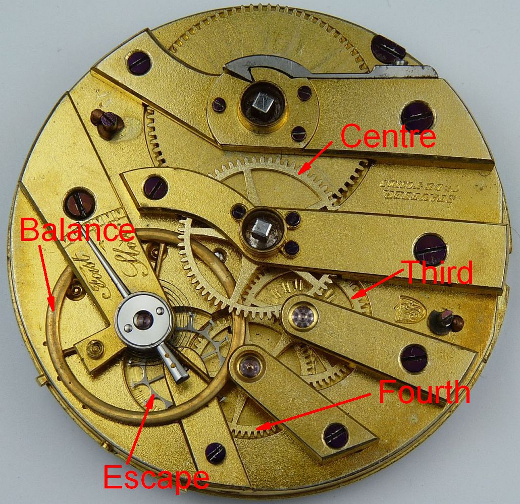
An early Stauffer movement with cylinder escapement. Such movements are usually anonymous. Click image to enlarge.
How can you tell if a watch has a cylinder rather than a lever escapement? The picture here is of an old movement with cylinder escapement. This is a mid nineteenth century movement and later movements may look different, but their wheel trains are the same so ignore the shapes of the cocks and bridges and concentrate on the wheels.
Start at the pivot of the centre wheel, the one right in the middle of the movement, then identify the pivots of the third and fourth wheels. The next wheel in the train is the escape wheel, and in this movement the pivot for the escape wheel arbor is underneath the balance – the red arrow labelled "escape" is not pointing to the balance but to the grey steel escape wheel that is below the balance.
The teeth on the escape wheel engage directly with the cylinder, which is part of the balance staff. There is no lever between the escape wheel and the balance staff as there is in a lever escapement, so the escape wheel of a cylinder escapement has to be planted right next to the balance staff. The escape wheel of a cylinder escapement also has its teeth shaped like those shown in the diagram from Saunier above.
Although the performance and longevity of Swiss made cylinder escapements with steel escape wheels and steel cylinders was better than English ones with brass escape wheels and steel cylinders, the difference is relative rather than absolute; the cylinder wears more slowly with the Swiss steel escape wheel, but it still does wear as the oil picks up dust and turns to a fine grinding paste. They were also usually at the lower end of the price scale so the train pivots are not jewelled. Jewels in watch movements are not just there to look pretty, or even to reduce friction; their principal role is to provide a hard bearing surface the reduces wear. An watch without train jewels needs servicing more than one with jewels if wear of the bearings in the plates is going to be kept within acceptable limits.
The only way to delay the inevitable is to have the movement regularly serviced, when it will be cleaned to remove the old mixture of oil and dust and lubricated with fresh clean oil. This should be done before the performance starts to deteriorate noticeably, because by then the damage can have been done, and replacing a cylinder is a job that fewer and fewer watch repairers are prepared to do. Even if you can find someone who will take on the task, it may be uneconomic because, in the main, watches with cylinder movements are not very collectible and therefore not highly valued - although if the item is a family heirloom this shouldn't matter.
The first watchmaker to make great use of the cylinder escapement was Jean Antoine Lépine who used them in watches that were, at the time, sensationally thin. With his designs Lépine created the modern watch and deserves to be far better known than he is. Lépine's designs formed the basis for the vast majority of French and Swiss watch production in the late eighteenth and through the nineteenth century. There is some information about dating Lépine calibres on the page about Jean Antoine Lépine.
The great Abraham Louis Breguet overcame the problem of wear in the cylinder escapement to a very great extent by making his cylinders of ruby, but don't expect to find such an exotic device in a cheap Swiss watch.
If you contrast this picture with that of the lever escapement at the head of this page, concentrating on the escape wheel and the cock that holds its upper pivot, you will soon be able to see the difference.
Back to the top of the page.
Stop Work and Recoiling Clicks
Stop work limits the range of winding of a watch mainspring, in particular the degree to which the mainspring can be wound up. In a watch with a fusee, this is necessary to stop the fusee chain riding out of the groove at the top of the fusee cone. In a watch with a going barrel, it is used to prevent the excessive force that could be locked in at the end of winding when the spring cannot be wound any further.
A mechanical watch is driven by the power stored in a spring. This is called the main spring or mainspring to distinguish it from other springs in the movement, in particular the balance spring.
The mainspring is contained in a barrel with its inner end fixed to a central shaft called the barrel arbor. The outer end of the mainspring is fixed to the inner wall of the barrel. When it is wound up, the mainspring exerts a torque or turning force between the arbor and barrel. The arbor is prevented from turning by a ratchet, so the torque drives the watch train and escapement, making the watch run.
In almost all modern watches, the mainspring barrel has teeth on its outside, which drive the movement directly, and is called a going barrel. Some watches and clocks have a fusee, a cone shaped device that evens out the torque of the mainspring. In a watch or clock with a fusee, the mainspring drives the fusee through a chain, and the fusee drives the movement.
The ratchet allows the barrel arbor to turn in only one direction. This is used when winding a watch. Winding turns the arbor, causing the spring to wrap tighter around the arbor, increasing the energy stored in the spring and the turning force on the barrel. The ratchet stops the arbor from turning backwards when winding is finished.
When the mainspring is fully wound, any further turning force cannot be absorbed by the spring and instead goes directly into driving the train. If force continues to be applied to the winding mechanism, this is transmitted directly to the wheel train and the escapement, producing excessive balance amplitude which can damage the escapement. For this reason, you should stop winding a mechanical watch as soon as the sharp increase of resistance is felt at the end of winding, when the spring is fully wound.
Mainspring operating range
Click image to enlarge
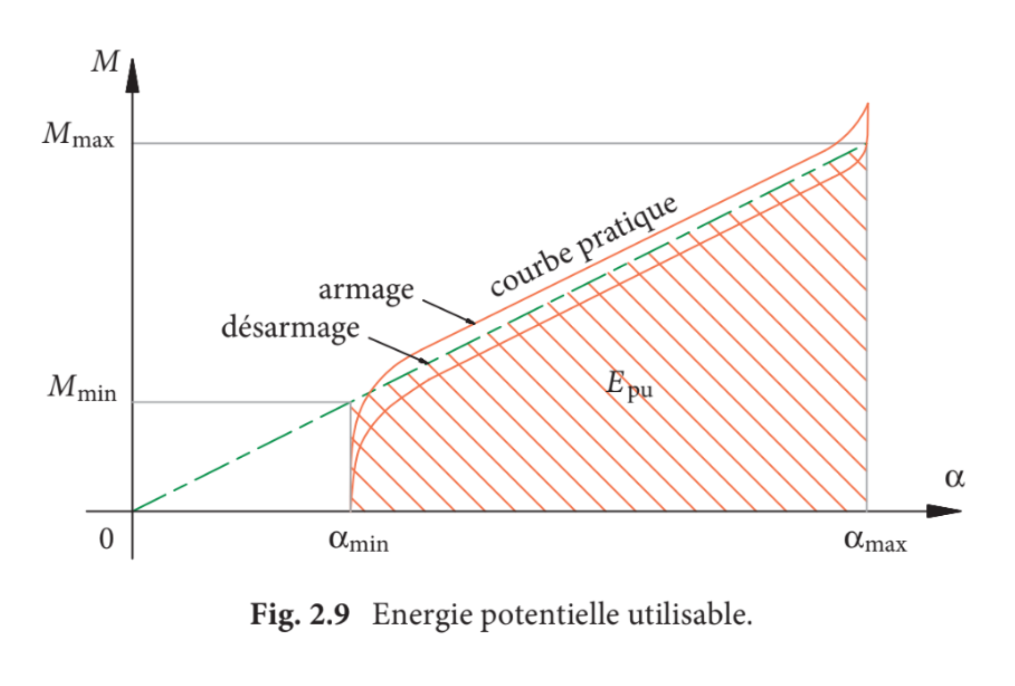
The torque exerted by a mainspring is not constant as the spring unwinds. In the middle part of its range it closely follows Hooke's law; the torque is proportional the angle of rotation of the barrel. But at the extremes, when the spring is either tightly wound around the mainspring barrel arbor, or almost fully uncoiled so that it is resting against the barrel wall, the variation is no longer linear as shown in the diagram here, due the way the spring is attached to the barrel and arbor.
If the spring is wound fully and tightly around its arbor, the very high torque that this creates can cause the balance to turn further than it should and the impulse pin to strike the outside of the lever fork. This not only results in inaccurate timekeeping but can also damage the escapement. To prevent this, either ‘stop work’ is used to stop the mainspring being wound tightly around its arbor, or a recoiling click is used to back off the mainspring a little before damaging amplitude can build up.
To avoid the very low torque when the spring is near fully unwound, when the frequency of the balance would be affected, the spring is sized so that a manually wound watch will go for around 36 hours, on the assumption that the owner will wind it every 24 hours and hence the last portion of the unwinding outside the optimum operating range will not be encountered in normal use.
There is a common misunderstanding about stop work. It is often said that its purpose is to limit the operating range of the spring to its middle part, or to prevent the spring from unwinding beyond a point where its increasing weakness causes the watch to lose accuracy. This is not correct, but it is often repeated and needs to be discussed, so I have included a discussion at the end of this section in Myth About Stop Work
Maltese Cross or Geneva Stop Work
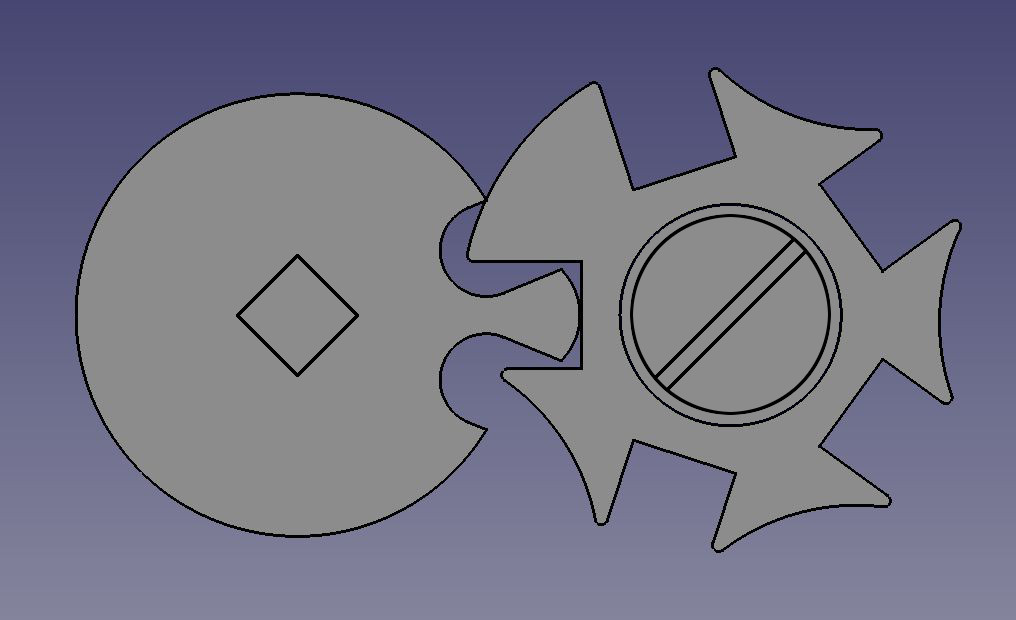
Maltese Cross, or Geneva, Stop Work
Maltese cross, or Geneva, stop work limits the turning of the spring barrel so that the very high torque caused when the mainspring is wound tightly around its arbor at the end of winding is avoided. The picture here shows the general arrangement, the part to the right is supposed to resemble a Maltese cross, which is where the device gets its name from.
The piece with the projecting finger sits on a square section of the arbor so that it must rotate with it. The piece shaped vaguely like a Maltese cross is attached to the spring barrel by a shouldered screw and is free to rotate. As the spring is wound and the arbor rotates relative to the spring barrel, the finger engages with each of the slots in turn and turns the cross. One of the arms of the cross is wider than the others and when this is encountered it locks against the finger piece on the barrel arbor, as is shown in the picture, preventing the spring barrel from turning any further.
The same thing happens in reverse as the spring unwinds, the finger piece turns the cross until the wide arm is reached in the opposite direction and further rotation is blocked. At this point the spring barrel can turn no further and the watch will stop. This is the source of the myth discussed below, that the purpose of stop work is to prevent the watch using a weak part of the spring that would make timekeeping less accurate. However, this is a feature of the way the stop work operates; it is not its main purpose, which is to prevent the mainspring from being wound too tight.
The stop work patented by IWC in 1904 in Swiss patent CH 31457 Dispositif pour limiter le remontage des mouvements d'horlogerie à barillet, or device for limiting the winding of a watch movement barrel, is a variation of this type of stop work called ‘geared stop work’. Instead of the Maltese cross and finger piece, which allow only a small range of adjustments to the operation of the stop work, gears are used. This allows the number of turns that the barrel can make before it is stopped to be varied, and allows finer adjustment of the exact point in winding at which the stop operates when the spring is being wound. Rather strangely I have never seen the IWC patented stop work, all IWC watches with stop work seem to have conventional Maltese cross stop work.
Recoil Clicks
The function of stop work with a going barrel was to prevent excessive force from the mainspring when it was fully wound. Stop work prevented the spring from being fully wound, but was a complicated way of achieving it, and it also stopped the watch if the owner was late in winding it. The invention of the recoiling click, which allowed the mainspring barrel to reverse slightly after the spring was fully wound, achieved the same end with much less complication and cost.
In watchmaking terms a click is a pawl that lets a toothed or ratchet wheel turn in one direction but blocks it from turning in the other direction. A recoil click in the keyless work is designed so that when the mainspring is fully wound, the click allows the barrel to turn backwards slightly, to "recoil", and let the mainspring uncoil a little from being fully wound. This removes the sharp increase in torque shown at the right hand side of the graph at the 100% wound position.
In 1877, Charles Haseler, of Aston, near Birmingham, who probably worked for the English Watch Company, was awarded a patent for a recoiling click. Haseler explained that in a going barrels without stop-work, when the mainspring is wound up to its full extent, it is in ‘a state of extreme tension’ until the spring hss slightly relaxed. The solution was to make the pivot hole in the click elongated so that when winding is finished, the pawl can slide backwards, allowing the barrel to turn a little, relieving the extreme tension.
High quality watches continued to be fitted with stop work; not because it improved timekeeping but because stop work was expected on a high qulity watch. In 1881, Henry Ganney, a member of the British Horological Institute and forthright commentator on horological matters, reported,
Noticing the absence of stop-work from Mr. Guye's second quality work, I was told they only put it to their best work in deference to general prejudice on the stop-work question ; but as a matter of fact the watches kept a better rate without stop-work, as fewer main-springs broke, as the extra width obtained by the suppression of the stop-work gave a strength and elasticity unobtainable otherwise. With such testimony it is useless to contend, and the sooner watch buyers and wearers are enlightened on the subject the better, and with the stop-work will disappear a cause of much trouble to repairers.
Automatic Winding
Automatic watches, which are constantly being wound while they are worn, have a mainspring that is designed to slip in the spring barrel when it is fully wound to avoid over straining the winding mechanism. The grease used has to be the correct grease to allow just the right amount of slippage. If the grease dries out and the spring can't slip, then the automatic winding mechanism can damage itself or the barrel; another good reason for getting a watch serviced regularly.
Myth About Going Barrel Stop Work
There is a common misunderstanding about the purpose of stop work used with a going barrel such as the Maltese Cross or Geneva mechanism. It is often said that its purpose is to limit the operating range of the spring to its middle part, to prevent the spring from unwinding beyond a point where it becomes too weak and causes the watch to loose accuracy. This is not correct.
Although the effect of stop work is to limit the operating range of the spring to its middle part, this is not its purpose. The fact that stop work prevents the mainspring of a going barrel from fully unwinding is an unwanted consequence of the design that is a nuisance and provides no benefit.
The principal purpose of stop work is to prevent the barrel being further wound at the end of winding. This is to avoid the high torque caused when the mainspring is wound tightly around its arbor. But of course, by limiting the number of turns the barrel can make, the stop work will stop the barrel turning before the spring is fully unwound, thereby stopping the watch. This is a consequence of the design rather than its primary purpose.
Rather than preventing a loss of accuracy, stopping a watch results in a total loss of accuracy, which is an inconvenience and annoyance to the owner.
As the mainspring of a going barrel (i.e. no fusee) unwinds, its torque reduces and the amplitude of the balance also reduces. With a manually wound watch this usually happens every 24 hours, between when it is fully wound and when it is run down before it is next fully wound. The effect of this variation in amplitude between fully wound and run down on timekeeping is minimised by making the balance and balance spring assembly as near to "isochronous" as possible, within the normal operating range of the mainspring.
Although a watch maintains its rate less accurately, and therefore keeps time less well, if it operates with the spring run down so that it is outside the range for which the balance is isochronal, the watch is still of some use to its owner. It might lose a few minutes, but it can be wound and corrected to time when the opportunity presents itself. However, a watch that has stopped has totally lost accuracy and is useless.
A stopped watch is of no use to its owner whatsoever. In fact is a positive nuisance because, in addition to winding it, the owner must then find a reference time to set the it correctly against. Today this is easy, but in earlier times, when stop work was common, it was not so easy to find a clock or a sundial.
In case this discussion does not convince, I quote George Daniels (Watchmaking, p284) ‘If the barrel is without stop work, then some form of resilient or recoiling pawl is necessary to relieve the pressure of the fully wound spring.’ Also, in Britten (Watch & Clockmaker's Handbook, 16th edition, p38), ‘To avoid high torque when the mainspring is tight wound about its arbor, various stop work devices can be used.’
In the Horological Journal June 1884, T. D. Wright wrote ‘The Winding of Watches. I have had a number of high-priced American watches through my hands, and have been surprised to find in every case that the barrel had no stop-work. There are some advantages gained in having no stop at the “down” position, because if a wearer forgets to wind his watch at the usual time, it will go many hours longer ; but every good watch should have a stop to prevent excessive winding up.’ These watches were fitted with recoiling clicks, American watchmakers finding no benefit to timekeeping of more complicated stop work.
Back to the top of the page.
Fusee
Early spring driven timepieces didn't have balance springs. This meant that their balance had no inherent natural frequency, it was simply flicked back and forth by the escapement. The time that each movement took depended on how hard the escapement pushed on the balance, so the rate varied greatly if the driving force from the mainspring changed.
To keep the rate of such a timepiece fairly constant, a fusee was introduced between the mainspring and the train. A fusee is shaped like a cone and connected to the mainspring barrel by a chain. When the mainspring is fully wound and its tension at its greatest, the chain pulls on the smallest diameter part of the fusee cone. As the mainspring runs down and its force diminishes, the part of the fusee cone that the chain pulls on increases proportionally in diameter. This keeps the force applied to the train, and hence to the balance by the escapement, constant.
When the balance spring was introduced, the combination of balance and spring had a natural frequency that resisted changes in its rate due to variations in the force exerted by the train. Improved designs of escapement reduced the influence of the force of the mainspring further, culminating in the 1820s in England with the highly detached English lever escapement. A fully detached balance with a perfect spring would be isochronous, i.e. would oscillate with the same frequency irrespective of amplitude, but no practical watch balance can achieve this because it needs to be impulsed by the escapement to keep going, introducing “escapement errors”, and because the balance spring has to be attached at both ends. However, improved designs increasingly approached the ideal.
Escapement errors increase as the amplitude of the balance decreases. John Arnold and Breguet recognised that the shape of the outer coil of the balance spring could be altered using the point of attachment effect to reduce the error and improve isochronism. With these developments, the detached lever escapement and overcoil balance spring, the improvement in timekeeping of an ordinary watch from employing a fusee was negligible. However, English watchmakers throughout the nineteenth century persisted with the fusee – but why?

Marine chronometer compensation balance
There was one branch of English horology where the fusee was not an unnecessary complication but a vital necessity. Marine box chronometers could not achieve the required level of precision in their timekeeping without it. But these machines had very highly detached spring detent escapements, and balance springs with carefully formed terminal coils, so were their balances not isochronous? No. Because as part of their means of compensating for variations in temperature the rims of their bimetallic balances were cut through in two places.
The dotted lines on the figure here shows how a cut bimetallic balance compensates for changes in temperature. When the temperature rises the balance spring gets weaker, so the bimetallic sections curl inwards to reduce the moment of inertia of the balance. The opposite happens if the temperature rises. The problem is that cutting the rim like this also allows the rims to flex outwards as the balance swings.
While the movement is working, the balance is stationery at two places during every oscillation at either end of its swing. When the balance stops the balance spring accelerates in back towards the central point where it unlocks a pallet and receives impulse. As this occurs the balance is rotating with increasing speed and the momentum of the rims and masses causes the rims to flex outwards. This increases the moment of inertia of the balance which affects the period. If the amplitude is always exactly the same, then this does not matter because the effect will be exactly the same on every cycle. But if the amplitude varies, then the speed of the balance as it passes through the central point will vary, so the effect will be different and affect the period.
Kullberg's Experiment
In 1887 Victor Kullberg, of the eponymous and famous box chronometer making company, asked the Astronomer Royal to rate a chronometer as it was fitted with four different balances. The chronometer was an ordinary large two day type and it was deposited at the Observatory on 18 April. With it were four balances of practically the same diameters but different constructions.
- A plain brass balance, not cut, with four quarter timing screws. Thickness of rim: 0.085 inch.
- An ordinary compensation balance, two timing screws and two compensation masses. Thickness of rim, 0.038 inch ; length of acting laminae 135° ; distance of centre of compensation masses 98° from bar.
- A steel balance with brass inlaid, two timing screws, two compensation masses. Thickness of rim, 0.035 inch ; length of acting laminae 141° ; half the laminae on each side compensated next to bar ; distance of centre of compensation masses 100° from bar.
- Same as No. 3 but with laminae 0.024 inch thick ; acting length of laminae 150° ; two small screws at ends of acting laminae, each weighing three grains ; distance of centre of compensation masses 61° from bar.
The amplitude of the balances in the long arcs was one turn and a fifth, and in short arcs three-quarters of a turn. The last three balances were accurately adjusted for temperature, and as the variations of temperature were so small, it can be assumed that the rates are unaffected by temperature. When balance No. 1 was fitted, the chronometer was placed in the oven at an even temperature. Below are the mean daily rates :-
| Long arcs | Short arcs | Difference | |
|---|---|---|---|
| Balance 1 | -166.4 | -174.5 | -8.1 |
| Balance 2 | +0.5 | +2.6 | +2.1 |
| Balance 3 | +6.1 | +21.6 | +15.5 |
| Balance 4 | +9.3 | +39.7 | +30.4 |
Kullberg's experiment showed that variations in amplitude had a significant effect on rate, which is why a box chronometer must be fitted with a fusee to keep the amplitude constant. Watches, being much smaller, do not suffer this effect to any significant extent. Watches also have to be adjusted to keep a constant rate in different positions - e.g. dial up versus pendant up - in which the amplitude is inevitable different. For these reasons a fusee is not required in a watch, but English watchmakers persisted in fitting them, increasing the size and cost of their watches.
Winding a Fusee or Going Barrel
If you are looking at the back of a English fusee key wound watch, which you will usually be when winding it, then the minute hand (if you could see it) would appear to be going anticlockwise. The great wheel turns the minute hand so, when viewed from the back of the watch, the great wheel must turn clockwise. The great wheel is mounted on the same arbor as the fusee and driven by the fusee cone through a ratchet. During normal running the fusee must also turn clockwise, so this is the direction in which the mainspring barrel must pull the fusee through the fusee chain. As the watch runs down, the chain is drawn off the fusee and onto the mainspring barrel, so when you wind the watch you need to reverse this by turning the fusee, drawing the chain off the barrel and onto the fusee cone, in the process winding the mainspring inside the barrel. So from the back of the watch you have to turn the fusee anticlockwise. Because you are turning the fusee rather than the barrel, it doesn't matter whether the spring barrel in a fusee watch turns clockwise or anticlockwise, in the "reverse fusee" the mainspring barrel turns in the opposite direction to the barrel in a standard fusee.
In a watch with a going barrel, the barrel, which has the great wheel teeth cut on its outside, turns the centre wheel which carries the minute hand. This must turn clockwise when viewed from the front, so the barrel must turn in the opposite direction, which means that when viewed from the rear of the watch the barrel must turn clockwise. The barrel arbor and the barrel both turn in the same direction; the arbor turns clockwise to wind the spring in towards the centre of the barrel, and as the spring uncoils it turns the barrel clockwise driving the train.
Important Note: Sometimes watches with going barrels had an extra gear incorporated so that the barrel was wound anticlockwise. This was to simulate the anticlockwise winding of a fusee watch for customers who thought that a fusee watch was the best but could only afford a going barrel watch, which were generally cheaper because they were simpler to make.
So the simple rule is: fusee watches are wound anticlockwise with a key; going barrel watches are wound clockwise with a key unless a gear has been inserted to make them wind anticlockwise. If you are not sure what you have got, examine the clicks, the pawls that allow the barel to turn in only one direction, to see which way to turn the key. If you can't see the clicks, then try turning the key gently in both directions, but bear in mind that if the watch is not running the mainspring might be already fully wound so don't force it.
Fusee Stop Work and Mainspring Set Up
The number of turns of the chain groove on a fusee is limited by practical considerations. The height of the fusee cone is restricted by the space between the plates, and the width of the groove is determined by the width of the chain. As a consequence, fusees are limited to a maximum of five or six turns.
The mainspring has to be sized taking the number of turns of the fusee into consideration. Because a watch with a fusee still has to run for at least 30 hours between windings, the gear ratio between the great wheel and centre wheel arbor is greater than with a going barrel. This higher gearing means that the mainspring for a fusee movement has to provide more torque and is shorter and thicker than one for a going barrel.
The mainspring must be sized so that it can make a greater number of theoretical turns than the fusee. The mainspring barrel and fusee must then be adjusted so that the mainspring is used in the centre of its range of turns with some spare at fully wound and fully unwound.
Like all watches, fusee movements are provided with stop work to prevent the mainspring from being too tightly wound. This usually takes the form of a finger that is actuated as the chain becomes fully wound and hits a stop fixed to the top plate of the movement.
To prevent the fusee chain becoming slack and potentially unhooking from the fusee at the end of unwinding, the mainspring is set up so that an amount of tension remains in the spring when the fusee chain is fully unwound. There are two ways of setting up the mainspring;
- As the chain is wound onto the barrel during assembly, when all the slack in the chain is taken up, the barrel is wound a further amount before the set up ratchet is secured; about three quarters of a turn. This method assumes that the mainspring is long enough that it is not fully wound before the stop work acts, which is difficult to check.
- The chain is wound fully onto the fusee, then the mainspring is wound fully and backed off a little before the set up ratchet is secured; about a quarter of a turn. This method assumes that the mainspring is long enough that some tension will remain in the spring and chain at the end of unwinding, which is easy to check.
With both methods, it is recommended that the torque produced at the fusee remains constant during unwinding. If it is lower when the spring is fully wound, the set up can be increased. If it is greater when fully wound, the set up can be reduced. If the torque is the same at fully wound and fully unwound but different at intermediate states, the shape of the fusee cone is wrong, but there is not much that can be done about this other than replacing the fusee.
Back to the top of the page.
Watch and Movement Sizes
English and American Watch Sizes
English and American watch sizes are based on the diameter of the bottom plate of the movement. The information here about English and American watch sizes is based on information in Philip Priestley's "Aaron Lufkin Dennison, An Industrial Pioneer and his Legacy".
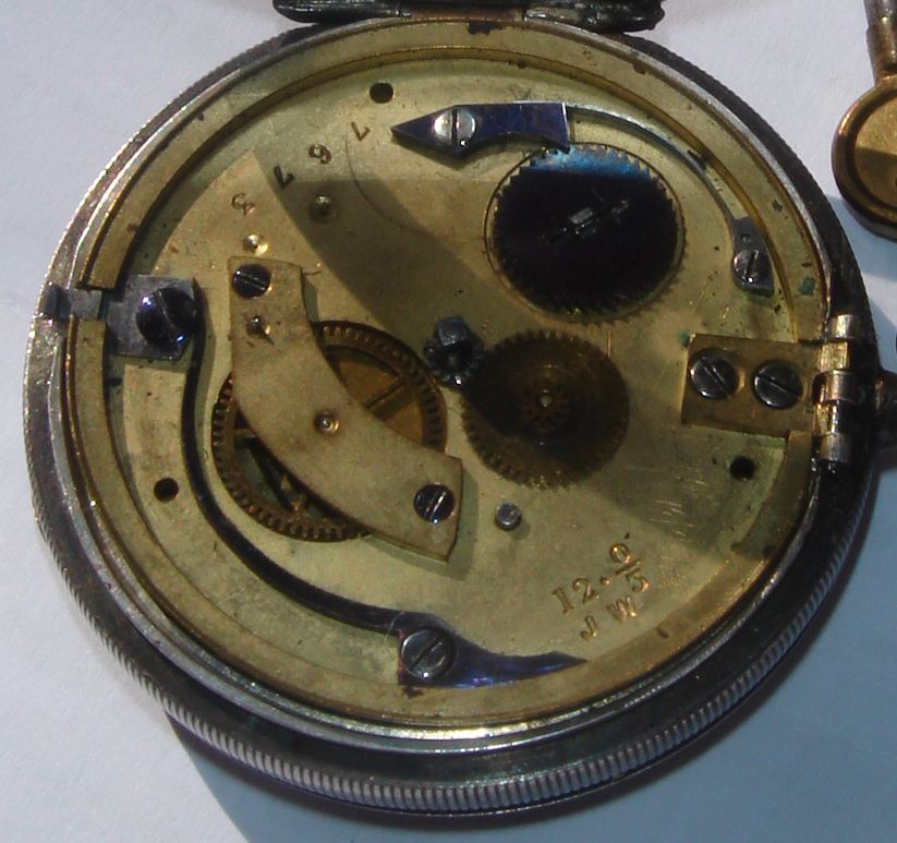
Wycherley movement underdial: Click image to enlarge
Thanks to Alan for the photo
The photograph here shows the dial plate of an English lever watch. The initials JW are for John Wycherley of Prescot, an English pioneer of mass produced rough movements. In 1866 Wycherley set up a factory in Warrington Road, Prescot, with three floors and steam power to produce by machinery plates and other parts that were interchangeable. Wycherley also introduced a system of uniform movement making with defined movement sizes, so that cases and dials could be ordered without having to send the movement for them to be made to fit.
Above Wycherley's initials are a set of numbers that define the essential dimensions of the movement, often called in English watchmaking the "calliper" of the movement, derived from the callipers used to measure the diameter of the bottom (dial) plate. The equivalent Swiss/French term is "calibre" and literally means much the same thing, although calibre is often used in reference to the specific layout of a movement as well as its size.
The first, larger, number on the plate is a 12. This gives the diameter of the movement. It is followed by a "pellet" • and then a zero over a 3 that gives the pillar height. The pillars in an old watch hold the top and bottom plates apart, so the pillar height determines the gap between the plates.
This calliper size is called the "Lancashire Watch gauge system" for determining watch sizes. Size zero formed the base of the scale with a plate diameter of 1 inch plus 5/30 inches for the mounting flange or "drop", giving a base for the scale at zero of 35 thirtieths of an inch, or 1.167″. Each 1/30 inch increased in diameter increments the gauge size by one. For smaller watches, the scale counts down from zero, indicated by 2/0, 3/0 etc. A glance at the table makes it clear.
The 12 on the Wycherley movement shown in the indicates that it is 1 inch plus (12+5)/30 = 1 and 17/30 inches in diameter, or 47/30 = 1.567″.
It might be thought odd that the gauge was based on 1/30 part of an inch rather than some less unwieldy fraction, but 1/3 of an inch was the smallest Anglo-Saxon unit of length and was called a barleycorn, because it was nominally the length of a corn or grain of barley. This measurement is still the basis for shoe sizes in Britain. When early watchmakers needed to specify dimensions more closely, it was natural for them to think in terms of 1/10 of a barleycorn.
| Size | Inches | Millimetres | Lignes |
|---|---|---|---|
| 10/0 | 26/30 = 1.000 | 22.0 | 9.75 |
| 9/0 | 27/30 = 1.000 | 22.9 | 10.1 |
| 8/0 | 28/30 = 1.000 | 23.7 | 10.5 |
| 7/0 | 29/30 = 1.000 | 24.6 | 10.9 |
| 6/0 | 30/30 = 1.000 | 25.4 | 11.3 |
| 5/0 | 31/30 = 1.033 | 26.2 | 11.6 |
| 4/0 | 32/30 = 1.067 | 27.1 | 12.0 |
| 3/0 | 33/30 = 1.100 | 27.9 | 12.4 |
| 2/0 | 34/30 = 1.133 | 28.8 | 12.8 |
| 0 | 35/30 = 1.167 | 29.6 | 13.1 |
| 2 | 37/30 = 1.233 | 31.3 | 13.9 |
| 4 | 39/30 = 1.300 | 33.0 | 14.6 |
| 6 | 41/30 = 1.367 | 34.7 | 15.4 |
| 8 | 43/30 = 1.433 | 36.4 | 16.1 |
| 10 | 45/30 = 1.500 | 38.1 | 16.9 |
| 12 | 47/30 = 1.567 | 39.8 | 17.6 |
| 14 | 49/30 = 1.633 | 41.5 | 18.4 |
| 16 | 51/30 = 1.700 | 43.2 | 19.1 |
| 18 | 53/30 = 1.767 | 44.9 | 19.9 |
| 20 | 55/30 = 1.833 | 46.6 | 20.6 |
| 22 | 57/30 = 1.900 | 48.3 | 21.4 |
The micrometer, with its associated division of the inch into “thous” or thousandths of an inch, was not invented until the nineteenth century. It might be thought that it would be difficult to make something as precise as a watch without a means of accurate measurement, but the first watches were made by hand finishing parts so that they all fitted together in one watch, they were not interchangeable between different watches. It was the development of accurate measuring instruments that allowed the mass production of watches, by enabling parts to be made to uniform sizes and interchangeable.
The Lancashire gauge system was adopted by American watch manufacturers, no doubt because before watches started to be manufactured in America, watches and watch movements were imported from England, and the Lancashire gauge size would have been used to specify the size of the movement, and hence the name for the size of the watch. American watches are referred to as, e.g. 16 size or 16S.
The gauge size is the diameter of the movement, not the size of the watch case, which is what you see and feel. A size 18 American railroad watch for instance should have a movement 1 + (18+5)/30 = 1.767 inches diameter, but the overall diameter of the case will be around 2.25″ or 56mm.
The 0 over 3 on the Wycherley movement indicates the pillar height, the distance separating the two plates of the movement. Standard pillar height was taken 1/8″ indicated as 0/0, with increments indicated above the line and decrements below in 1/144″. So 0 over 3 indicates a pillar height of 1/8″ minus 3/144″, or 18/144 - 3/144 = 15/144, that is about 0.104″ or 2.65 mm - which when I first worked it out seemed very small, but I have just put a rule to the movement of an English lever watch that was laying on my desk and the gap between the plates is 3 mm, so 2.65 mm doesn't seem out of the question.
Inches
It always seems fortunate that the conversion factor between inches, a unit based on one twelfth of the length of an Anglo-Saxon King's foot, or the width of a carpenter's thumb, or three barleycorns (whichever you prefer), and millimetres, which are based on the distance between the North Pole and the Equator along the meridian through Paris, should be exactly 25.4; a number that is nice and easy to remember rather than having a long string of decimal places. In fact this wasn't always so.
In Britain and Commonwealth countries, and in America, the inch was historically legally defined as one thirty-sixth of a yard. Before 1959 the British imperial yard and the American yard were not exactly the same, and consequently British and American inches were slightly different, and neither was exactly 25.4mm. In 1930 the British Standards Institution adopted an inch of exactly 25.4 mm, the American Standards Association followed in 1933, and by the mid 1930s many countries had adopted this “industrial inch”, but these remained industrial rather than legal standards.
In 1959 the “international yard” was defined as 0.9144 metres and this was adopted as the legal definition in Britain and Commonwealth countries and in America. An inch is one thirty-sixth of this yard, or 25.4mm. As a consequence, the American legal inch reduced by 2 millionths of an inch and the UK legal inch increased by 1.7 millionths of an inch.
Swiss and French Watch Sizes
Swiss and French watch movement sizes are usually given in lignes (pronounced ‘line’).
The symbol for lignes is the triple prime ‴ in a similar way to the double prime sign ″ for an inch. For example 13‴ means thirteen lignes, a common size for a man's wristwatch movement.
A ligne is 1/12 of an old French inch, which itself is 1.0657 of an English inch. So a ligne is about 2·256mm.
| Lignes | Millimetres |
|---|---|
| 10 | 22·6 |
| 10½ | 23·7 |
| 11 | 24·8 |
| 11½ | 25·9 |
| 12 | 27·1 |
| 12½ | 28·2 |
| 13 | 29·3 |
The conversion for a ligne is 2.2558291 mm (1 mm = 0.443296 ligne), which is more easily remembered as 2·256 mm.
Watches were made in sizes from 2½ lignes, a very small ladies' baguette movement, to 20 lignes or more for pocket watches. The catalogue ligne size given for a movement is often not an exact measurement, it is more of a general classification of size, so don't expect a 13‴ movement to measure exactly 29·3mm.
Note that the measurement of diameter must be made just below the flange on the bottom plate that holds the movement in the case.
Swiss made men's trench wristwatches from the First World War often have a 13 ligne movement, such as a Longines 13.34, and a case size of about 35mm diameter excluding the lugs and crown. This is a nice size even today when the fashion is for larger watches. The case is about 5½ mm larger than the movement.
A accurate conversion for a ligne to millimetres is 2.2558291 mm (1 mm = 0.443296 ligne), which is more easily remembered as 2·256 mm. The ligne was derived from a ‘douzième’ or 1/12 of an old French inch. In the context of watches, a douzième usually means a twelfth part of a ligne, also sometimes called a point. This can be measured with a douzième gauge.
References such as the Bestfit Catalogue list movements grouped into half lignes, or occasionally quarter lignes. The calculator below returns the ligne size to half a ligne, e.g. 12½ or 13 ligne. The quarter ligne sizes are usually very few for men's size watches and are tacked on to the end of the half ligne sections, for a small watch movement you might need the quarter size.
If you have any comments or questions, please don't hesitate to get in touch via my Contact Me page.
Copyright © David Boettcher 2005 - 2026 all rights reserved. This page updated April 2026.
Back to the top of the page.