About Watch Movements (2)
Copyright © David Boettcher 2005 - 2026 all rights reserved.This page is intended to go into some more technical details about watch movements.
The effects of temperature on the rate of a watch and attempts to compensate for this are such a large topic that I have made a separate page about temperature effects.
If you have any questions or comments, please don't hesitate to contact me via my Contact Me page.
The Balance Spring
The balance spring is the elastic element that gives the oscillating time controller, the balance assembly, its natural frequency. If that sounds a bit abstract it is easier to think of the balance assembly as simply two things; the balance that you see swinging backwards and forwards and the spiral balance spring that makes it swing.
The balance spring is attached at one end to the balance cock by the stud. The spring passes through a hole in the stud and is fixed in place with a pin, and the stud itself is the attached to the balance cock by the stud carrier. At the other end the balance spring is fixed to the balance staff by the collet, again passing through a hole in the collet and being fixed in place by a pin. When the balance turns from its rest position in either direction, the balance spring exerts a twisting force in the opposite direction, trying to return the balance to its rest position. If the balance is swinging freely, at some point the restoring force of the swing arrests its motion and accelerates it in the opposite direction. When the balance reaches its rest position, the spring no longer exerts any twisting force, but now the balance is turning quickly and it momentum carries it past the rest position to an opposite extreme where the force of the spring again arrests it and accelerates it back towards the rest position. In this way the balance is caused to swing backwards and forwards with a natural frequency, which is what determines the timekeeping.
Isochronism
When he first thought of using a balance spring around 1660, Dr Robert Hooke thought that it would make the watch an even better timekeeper than a pendulum clock. The balance of a watch swings backwards and forwards around a fixed axis and therefore does not suffer from the problem that prevents pendulums from being "isochronous".
In horological terms, "isochronous" means that the regulator that controls the timekeeping, whether balance or pendulum, will oscillate with the same frequency irrespective of the amplitude of its arc of vibration. A simple pendulum can't do this because of circular error. I don't propose to go into this in detail here, but it arises from the pendulum swinging in a circular arc but gravity always pulling vertically. In a perfect oscillator the restoring force is always proportional to the displacement but, because gravity pulls on a pendulum bob vertically rather than tangentially, geometry means that this condition is not fulfilled by a simple pendulum.
Robert Hooke had observed a property of springs from which he formulated "Hooke's law", which says that the force exerted by a spring is proportional to its extension. Hooke had realised that this property of springs could be used in watches and hoped to develop a commercial product so to prove the date at which he had the idea without actually revealing it publicly he recorded his discovery as a Latin cipher in an endnote in a book he wrote about helioscopes: "The true Theory of Elaſticity or Springineſs, ... ceiiinosssttuu." Hooke later revealed that this cipher encoded the phrase "Ut tensio sic vis" or "As extension so force", meaning that the force exerted by a spring is proportional to its extension. Hooke applied this idea to a watch in 1658 and attempted to secure a patent on the invention, but he encountered problems in getting a satisfactory patent and the idea remained on the back burner. In 1675 Christiaan Huygens announced that the timekeeping of watches could be dramatically improved if a spiral spring was attached to the balance. This kicked off a furious row with Hooke about which of them should have the credit for the invention, which has still not been entirely settled.
When a stationery balance with an attached spiral balance spring are rotated away from the rest position, the spring exerts a turning force in opposition to the rotation. When the balance is released at some point away from the rest position, the force of the spring accelerates it back towards the rest position. When the balance reaches the rest position the force from the spring is zero, but the momentum the balance has gained from being accelerated causes it to carry on rotating past the rest position. The spring then starts to exert a turning force in the opposite direction, which slows and eventually stops the balance, and then accelerates it in the opposite direction. If there was no friction the swinging back and forth of the balance and spring would continue for ever, the balance and its spring continually swapping between them the energy that was initially given when they were disturbed from their rest position. The balance and its spring form a simple harmonic oscillator whose regular oscillations can be used to measure time.
A spiral balance spring that obeys Hooke's law combined with a pivoted balance that is free to rotate about its axis means that the restoring force on the balance towards its rest position is always proportional to its displacement from that position, which would make a perfect harmonic oscillator; one that oscillates with a constant frequency irrespective of the arc of vibration. The frequency of such an oscillator would be immune to the change in amplitude that occurs as the power of the mainspring diminishes between windings, and as manufacturing techniques and balance springs improved, watch escapements approached this ideal.
Point of Attachment Effect

Archimedes' Spiral
A spiral balance spring attached to a balance does not exactly obey Hooke's law. The restoring force is not exactly proportional to its deflection, or degree of rotation in this case.
The relaxed shape of a flat balance spring is an Archimedes spiral, a form of spiral where the gap between each coils is the same. When a spring this shape the spring is wound, the spring wants to bend equally all along its length, which would mean the coils moving closer together or further apart. But the ends of the spring are fixed at the stud and collet, so this can't happen.
The balance spring is pinned to the collet on the balance staff so that its inner termination is not exactly on the centre line of the balance staff. The ends of the balance spring are also fixed at two radial distances from the centre of rotation, at one end in the stud, the other in the collet, and they can't change angle as the spring is coiled and uncoiled. When the balance rotates the balance spring, instead of coiling and uncoiling around a fixed centre point at the axis of the balance staff, has its inner end moved around in a circular path by the collet into which it is fixed.
As the balance spring "breathes" in and out, the fixed angles of the terminations in the collet and stud cause the coils to "develop" asymetrically; they bunch up or spread out on one side of the spring more than the other. This results in the restoring force exerted by the spring on the balance varying with different amplitudes of oscillation, which causes a lack of isochronism in positions or as the mainspring runs down over time and the amplitude of the balance decreases.
The angle between the point of attachment of the spring at the stud and collet affects the torque developed by the spring as it is bent while the watch is running, which means that the couple produced is not directly proportional to the angle of displacement. This affects isochronism, meaning that the rate is different at different amplitudes. This effect is used to counter the effect on isochronism of the escapement. The action of a lever escapement causes a loss which becomes more significant at lower amplitudes, so the Point of Attachment Effect is used to increase the rate of the sprung balance at low amplitudes to compensate for this.
This purely mechanical / elastic effect is different to the effect of gravity on the spring, which is called the Grossman effect. The Point of Attachment Effect was first studied in detail theoretically by Phillips and Lossier at the end of the nineteenth century.
It is sometimes said that the eccentric development of the balance spring affects the rate because it causes a side thrust on the balance staff pivots and alters the friction. This is not correct. Although there is friction at the balance staff pivots, there is always some side thrust and the effect of balance spring developing eccentrically will have only a small effect on this. The major effect on rate is the difference in torque resulting from different balance amplitudes.
Breguet Overcoil

Balance Spring with Breguet Overcoil: Click to enlarge
The earliest surviving Breguet watches have flat balance springs. Towards the end of the eighteenth century, Breguet improved the isochronism of watches by bending the outer coil of the spring upwards above the plane of the spiral and curving inwards so that it could be pinned closer to the centre of rotation of the balance.
The image here shows a balance spring that has been formed in this way. The coil which rises up and passes inwards over the other coils of the remaining flat part of the balance spring is called the “overcoil”. A balance spring with this feature is often called a “Breguet overcoil balance spring”. In Swiss French this is a “Spiral Breguet”.
The overcoil resulted in the balance spring “developing” more symmetrically about the balance staff, expanding and contracting more evenly as the balance swings backwards and forwards and the spring winds and unwinds, which improves isochronism. By altering the shape of the overcoil, the relationship between the pinning points of the spring into the stud and the collet can be altered. This so called “Point of Attachment Effect” is used to correct for escapement losses.
The action of unlocking the escapement and impulsing causes a losing rate over part of the swing of the balance called the “lift angle”, which is a constant number of degrees of balance rotation depending on the escapement design. If the balance amplitude reduces, either due to a change in position from horizontal to vertical or the reduction of mainspring torque during the 24 hour run, the proportion of the total swing over which the escapement loss occurs increases.
By adjusting the overcoil so that it causes an increase in rate at lower amplitudes through the point of attachment effect, the loss due to the escapement can be offset. This is the work of the “springer and timer”, by far the most important person in the production of a fine hand-adjusted watch or chronometer.
Back to the top of the page.
Escapement Effects
If the balance and balance spring were set in motion and not interfered with, then the balance would swing back and forth at the natural frequency of the assembly. But it would also slow down and eventually stop as a result of the small but inevitable amount of friction at the pivots of the balance staff, and due to disturbing the air. So there has to be a means of adding energy to the balance to replace the energy lost to friction, and also there has to be a means of recording each swing of the balance so that this can be used to display the time. The escapement performs both functions; as the balance passes through its zero position it unlocks the escapement, which allows the train to advance one tick and move the hands a corresponding amount, and the escapement gives the balance a little push called an impulse that makes up the energy it has lost during its swing.
The actions of unlocking and impulsing the balance affect its period of oscillation. The action of unlocking has to occur before the zero point, and it takes energy from the balance which causes a loss. If the impulse could be delivered instantaneously to the balance exactly as it passed through the zero point, then it would have no effect on the period. But this is not possible and the impulse is delivered over a finite period while the balance moves through a small angle of rotation. Part of the impulse is delivered before the zero point, which causes a gain, but the greater part of the impulse is delivered to the balance after it has passed the zero point and causes a loss.
The changes in period and rate due to unlocking and impulse are traditionally called "escapement errors". In the lever escapement they result in a losing rate compared to the natural frequency of the balance.
Back to the top of the page.
Effects of Position

Balance in Crown Down Position

Balance in Dial Up Position
Although a wristwatch can assume lots of positions, there are two orientations that have a big difference in amplitude, which can affect the rate, and hence the timekeeping, if the balance is not isochronous and because of escapement error.
These two positions can be characterised as "dial up" such as when you are sitting at a desk writing and the dial of you watch is on the top of your wrist, and crown down, such as when you are standing up with your arm hanging down so that the crown is facing the floor and the dial is vertical. The amplitude when dial up is usually 270° or more, when crown down it can fall to 220°. The escapement error takes place over a fixed angle, so as the amplitude falls it has a greater effect.
In the dial up position, as shown in the first drawing, the balance staff is vertical so all the weight of the balance is taken on the point where the rounded end of the staff sits on the cap jewel, indicated by the red arrow. In this position there is virtually no frictional torque acting on the balance staff. Frictional torque, the amount of friction that acts to retard the turning of the balance staff, is determined by the amount of friction multiplied by the length of the torque arm over which it acts. In the dial up position, although all the weight of the balance is taken on the end of the balance staff, so the friction is considerable, because the end of the balance staff is rounded where it contacts the cap jewel, the length of the torque arm is virtually zero, so the frictional torque is also virtually zero.
In the crown down position, as shown in the second picture, the weight of the balance is taken where the balance staff sit on the sides of the two jewel holes, as shown by the two red arrows. There is a lot more frictional torque in this position than in the dial up position because the torque arm over which the friction operates on the balance staff is the radius of the balance staff itself. Although this is small, it is still a lot greater than the length of the torque arm acting in the dial up position, which as we saw above is virtually zero.
The loss of amplitude cannot be prevented, but careful engineering of the balance and jewels can minimise the effect. This is the principal reason why the pivots of the balance staff are made so thin and the jewel holes are olives: the thinner the pivot the shorter the torque arm, and the olive shaped jewel has a smaller area of contact with the pivot than a jewel with a cylindrical hole. The less friction there is in the crown down position, the less is the effect of changing attitude.
So there is more friction at the balance staff pivots when the watch is vertical than when it is in the dial up or down position. Does this mean that the watch will run slower? Well, it shouldn't. The balance will have a smaller amplitude in the crown down position than in the dial up position but if the oscillator, the balance and its spring, are truly isochronous, then their frequency of vibration should be the same whatever the amplitude. However, perfect isochronism is difficult to achieve and there are always the escapement errors, and a watch that is keeping time in the dial up position can have a different rate in the crown down position.

Vulcain Conical Endstone
The Vulcain Watch Co. patented endstones that are cone shaped with the apex off centre. The object is that when the movement is horizontal the balance staff pivots are pressed against the sides of the jewel holes and the increased friction becomes closer to the friction of the pivots bearing on the sides of the holes when the movement is in the vertical position. It was claimed that more accurate positional timing was obtained and that errors were reduced by as much as 50 per cent. However, the deliberate introduction of extra friction in this way is not regarded as good practice and the design was not widely used or copied.
Back to the top of the page.
Tourbillons and Karrusels
The Tourbillon and Karrusel mechanisms were created to address a specific problem: a balance that is out of 'poise'. If a balance is out of poise, in simple terms one side is heavier than the other.
When a watch is oriented so that is is vertical, an out of poise balance introduces an element of 'pendulum like' behaviour which affects its rate. If the watch is turned from pendant up to any other vertical position, the rate changes, which it also does if the amplitude changes, e.g. when it decreases as the mainspring runs down.
Out of poise errors can usually be eliminated by careful poising of the balance. But compensation balances are impossible to poise because the screws or masses that are used to adjust the temperature compensation cannot then be moved to achieve poise without affecting the compensation.
There is some dispute about who invented the Tourbillon, Breguet or John Arnold. This seems to be based on a watch made by Arnold to which Breguet fitted a Tourbillon. Why this would suggest that Arnold invented the Tourbillon escapes me. On the 7th of Messidor Year IX (26 June 1801 ) the Ministry of the Interior of France granted Breguet a patent for design where the balance and escapement of a watch was rotated in a cage as the watch was running.
In 1892 Bahne Bonniksen (1859-1935), invented a simpler form of tourbillon which he called a “Karrusel”.
By rotating the balance the effect of the heavier side moves repeatedly around all the vertical positions, a tourbillon evens out the poise effects when the watch is in different vertical positions, so that the long term rate when on edge is constant irrespective of the pendant position. The traditional forms of tourbillon and Karrusel are ineffective in changes of position from vertical to horizontal, e.g. from pendant up to dial up.
Poise errors have no effect when a watch is dial up or dial down and the balance is horizontal. This is why marine chronometers, which are always kept dial up by gimbals, were not fitted with Tourbillon or Karrusel mechanisms.
It is interesting to note that the usual form of tourbillon has absolutely no effect on a change of position from vertical to dial up or down. A single axis tourbillon turns the balance to iron out the effects of poise. But it only turns it in one plane. It has no effect on the much greater positional effect of the change from dial up to vertical. Tourbillons with inclined cages and two and three axes of rotation have been made, which do counter position effects by putting the balance into all positions from vertical to horizontal irrespective of the orientation of the watch.
Back to the top of the page.
Magnetism
Magnetism can have an effect on the timekeeping of a watch if the balance or balance spring become magnetised. If the balance becomes magnetised the cross bar can act like a North/South magnet and try to align itself with the earth's magnetic field. This will cause the watch to run fast or slow depending on the direction it is pointing. If the balance spring becomes magnetised, this can cause the coils to stick together.
In the nineteenth century, magnetism was sometimes thought to be a particular concern for chronometers on iron ships. However, the earth's magnetic field is too weak to act on an unmagnetised balance, and before the age of electricity it was not easy for a balance to become accidentally magnetised.
When iron hulled ships were introduced there was a concern that magnetism from the ship might have an effect on the chronometers, but this fear wasn't realised. Iron in the hull or structure of a ship does become magnetised during construction. This has an effect on compasses carried on board, which are sensitive to magnetic fields because the compass needles are magnetised for this very purpose. But so long as the balance of a chronometer was not itself magnetised, the earth's and ship's magnetic fields have no noticeable effect on it.
The rate of a chronometer can be affected by bring a magnet close to it, so it might be throughout that the magnetism of a ship would also have an effect. This is not the case for the following reasons. Compasses, which are sensitive to magnetic fields because their needle is magnetised, continue to work on iron ships. They do need to be checked and corrected for the ship's magnetic fields, but this shows that the earth's magnetic field is stronger than the ship's – if it wasn't, a compass wouldn't work at all. The rate of a chronometer can be affected by a magnet brought close to it. This is because the magnet induces temporary magnetism into the steel parts of the chronometer. When the magnet is removed the temporary magnetism disappears and the rate returns to normal. A strong magnet can induce permanent magnetism into steel, but then the effect on the chronometer's rate is permanent and noticeable. The earth's magnetic field is not strong enough to induce either permanent or temporary magnetism into chronometers, if it were then they would all be useless, whether on ship or on land. And therefore, a ship's magnetic field, being weaker than the earth's, can have no effect on a unmagnetised chronometer.
In 1840 the Astronomer Royal Sir George Airy reported one chronometer, Brockbanks No. 425, that had become magnetised and which altered in its rate depending in which direction it was oriented. Evidently the balance arm had become magnetised so that when the neutral position was aligned with the earth's magnetic field it was faster than when it was at 90°.
How the chronometer had become magnetised is not mentioned in Airy's report, it may have been due to a lightning strike on the ship in which it was being carried. Before electricity was generated and distributed, lightning strikes were the only sources of large electrical currents and magnetic fields that could magnetise a chronometer. Naturally occurring lodestones that are magnetic were most likely themselves magnetised by lightning strikes. At the time there was no easy way to demagnetise the chronometer but Airy showed how t could be corrected by placing a compass beneath it. The field of the compass needle opposed the earth's field and the two effects cancelled each other.
With the age of electricity it was much easier for watches to get exposed to strong magnetic fields and non-magnetic watches were produced. These either had balances and springs that were made from non-magnetic material, or the movement was encapsulated in a "soft iron" enclosure – the iron is magnetically soft, not physically soft; it remains "as hard as iron".
Demagnetising watches that have become magnetised is, in principle, quite simple. A BHI Honours Grade sample answer from 1899 gives the following methods. "The parts of a magnetised watch may be separately demagnetised by using bar magnets of different sizes. The polarity of the piece must first be ascertained, then the repelling pole of the largest magnet brought close to the piece. This may have the effect of entirely reversing the magnetism. If so, then the opposite pole should be advanced, but not quite so close as at first. The weaker magnets should then be used, keeping them more distant as the magnetism grows more feeble. This method is a very tedious one. A better way is to fix a strong horseshoe magnet to the chuck of a lathe, bring the watch between the poles, and slowly withdraw it while the magnet is rapidly revolving. The best way is to place the watch inside a solenoid through which an alternating current of electricity is passing, and to slowly withdraw the watch while the current is still flowing. The principle in all these methods is to subject the magnetised object to reversed currents which grow gradually weaker and weaker until they cease to have any sensible effect."
Fortunately, the age of electricity also brought with it an easy means of demagnetising a watch that has become magnetised. The watch is placed in the alternating magnetic field of a purpose made demagnetiser and slowly removed, which removes the magnetism. But this needs a trip to a watchmaker who has a demagnetiser, which can be avoided if you take care not to expose an old watch to a magnetic field. Modern watches are made resistant to magnetism.
There is more about the general topic of magnetism on a page on my personal web site at DavidBoettcher.uk/magnetism.
Back to the top of the page.
Vibrations
Each swing of the balance from the centre to the point where it reverses and then returns to the centre is called a vibration or beat.
At the start of each vibration, as the balance swings through the centre line, a line joining its axis of rotation to that of the escape wheel, the impulse pin moves the lever and a tooth of the escape wheel is unlocked by a pallet and ‘escapes’. The shape of the pallet face and escape wheel tooth are designed so that, after unlocking, a push called an ‘impulse’, is given to the balance, replacing energy lost by friction. After the escape wheel has turned slightly, the other pallet catches a tooth of the escape wheel and the lever hits the banking pin, locking the escape wheel. The process of unlocking and locking generates an audible tick.
| Vph | 14,400 | 16,200 | 18,000 | 21,600 | 28,800 | 36,000 |
|---|---|---|---|---|---|---|
| Ticks/second | 4 | 4.5 | 5 | 6 | 8 | 10 |
| Ticks/minute | 240 | 270 | 300 | 360 | 480 | 600 |
| Frequency (Hz) | 2 | 2.25 | 2.5 | 3 | 4 | 5 |
| Period T (seconds) | 0.5 | 0.44 | 0.4 | 0.33 | 0.25 | 0.2 |
Escapements are often characterised by their “vibrations per hour” (vph), sometimes shortened to simply vibrations, or beats per hour (bph). Very old pocket watches run at 14,400, 15,400 or 16,200 vibrations per hour. The 18,000 vph escapement eventually superseded these in the nineteenth century.
For many decades 18,000 vph remained the standard, giving 5 vibrations or ticks per second, since with 3,600 seconds in an hour, 5 ticks per second = 3,600 x 5 = 18,000 vph. The relationship between vibrations and ticks per second is:
\[ vph = 3,600 \times \text{ticks per second} \]Each tick or vibration represents a swing of the balance from one extreme of its excursion to the other. In physics terms, a cycle is a complete swing of the balance one way and then the other way, returning to where it started, so an 18,000 vph, 5 vibrations per second, balance has a frequency of 2.5 cycles per second, called 2½ Hertz (Hz), and a period of 0.4 seconds.
An 18,000 vph escapement makes one vibration and gives one tick every 0.2 seconds, which is a half period or semiperiod. The relationship between vibrations and semiperiods is:
\[ vph = \frac{3,600}{semiperiod} \]Higher frequency escapements were used to give watches, especially chronographs or stop watches, greater resolution, which was useful for timing events accurately. Some of these ran at very high frequencies; hundreds of vibrations per second.
Half Second Ticks
The only place where higher frequencies were never used was in marine chronometers, which kept the 14,400 vph rate.
Marine chronometers have detent escapements which only unlock, and therefore move the seconds hand, on every other vibration. An 18,000 vph rate would move the seconds hand every 0.4 seconds, which would look odd since over a two second period the hand would move to 0.4, 0.8, 1.2, 1.6 and 2.0 seconds, and higher frequencies would be even more difficult to read precisely.
By keeping the lower 14,400 vph rate, the seconds hand of a marine chronometer moves every half second, which makes it easy to note down time readings to a half second.
High-Beat Watches
In the 1950s, higher frequency escapements were introduced to give watches better timekeeping stability. A higher frequency balance stores more energy and is therefore less easily disturbed. These operated at 21,600 vph then 28,800 vph, giving 6 or 8 ticks per second. When electric watches came along higher frequencies were introduced for mechanical watches such as the Girard Perregaux 36,000 vph movement of 1966 and the Zenith El Primero 36,000 vph movement of 1969. The high frequencies introduced problems of retaining lubrication on the pallet jewels, leading to the introduction of the thixotropic 9415 escapement grease.
Back to the top of the page.
Train Counts

Power Flow from Great Wheel to Escapement

Marvin Train Wheels: Click image to enlarge
The sketch shows in outline the flow of power from the great wheel through the train to the escapement. The large diameter items are the wheels, the smaller ones the pinions. You'll have to imagine that each wheel has teeth and each pinion has leaves.
The great wheel is mounted on either a fusee or, in movements without a fusee, a barrel. In either case, the mainspring drives the barrel, which applies torque to the great wheel, either through chain to a fusee or directly. The power from the mainspring flows through the train from the great wheel to the escapement, with each successive wheel turning faster, so each wheel drives the pinion of the next wheel. As the speed of the wheels increases, the torque that they deliver to the next wheel decreases.
The great wheel drives the pinion of the centre or second wheel. The minute hand is mounted on the arbor of the centre wheel, so it must turn once an hour if the watch is to keep time correctly. The hour hand is usually driven from the minute hand by the motion work under the dial.
The centre wheel turns the third wheel, and the third wheel turns the fourth wheel. The fourth wheel turns once per minute, or once every 60 seconds, so can be used for the seconds hand. In watches with a small seconds dial, the seconds hand is mounted on an extension of the fourth wheel arbor that projects through the dial. On watches with direct centre seconds, the train is arranged so that the fourth wheel is at the centre of the movement instead of the second wheel.
The fourth wheel drives the pinion of the escape wheel, which is locked by the pallets on the lever until a swing of the balance unlocks a pallet and the escape wheel advances by one tooth. From number of teeth on each wheel and pinion in the train you can work out how fast each wheel is turning and how many vibrations the escapement makes in an hour.
Typical trains have the tooth counts shown in examples in the table below, although other counts are often used.
The ratio of turns of the mainspring barrel or fusee to the centre wheel does not affect timekeeping so the tooth and leaf counts for the great wheel and the centre wheel pinion are not given for all cases. The photograph above shows the wheel train from a Marvin 18,000 vph movement with a barrel tooth count of 75 and a centre pinion count of 10. This ratio means that the centre wheel turns 7½ times for one turn of the barrel, which equates to seven and a half hours. To achieve a run of 30 hours between windings, which is typical for a mechanical watch, 4 turns of the barrel are required. However, the final turns of a barrel are less effective due to the mainspring setting around the arbor, so usually an extra 2½ turns are allowed to account for this.
| Vph | 28,800 | 18,000 | 14,400 | |||
|---|---|---|---|---|---|---|
| Wheel | Wheel teeth | Pinion leaves | Wheel teeth | Pinion leaves | Wheel teeth | Pinion leaves |
| Great | 80 | n/a | 75 | n/a | ||
| Centre | 75 | 14 | 80 | 10 | 64 | |
| Third | 72 | 10 | 60 | 10 | 60 | 8 |
| Fourth | 96 | 9 | 70 | 8 | 56 | 8 |
| Escape | 20 | 8 | 15 | 7 | 15 | 7 |
The relative speed of two wheels is given by the ratio of the number of teeth on the wheel and the number of leaves (teeth) on the pinion it is driving. For example, in an 18,000 vph train with 80 teeth on the centre wheel and 10 leaves on the third wheel pinion, the third wheel will turn 8 times as fast as the centre wheel.
An alternative way of looking at this is that the third wheel pinion will make one revolution when 10 teeth of the centre wheel have passed, one tooth for each pinion leaf. Since the centre wheel has 80 teeth it will rotate once for 8 turns of the third wheel.
The escape wheel has 15 teeth. For the wheel to make one complete revolution, each tooth has to pass both the entry and the exit pallet, so each tooth on the escape wheel needs two ticks to get back to where it started. An 18,000 vph train ticks 5 times per second, meaning that a 15 tooth escape wheel will need 30 ticks to make one revolution. Each tick takes 1/5 second, so a complete revolution of the escape wheel takes 30 x 1/5 = 6 seconds. The escape wheel will therefore rotate 10 times in one minute.
If the fourth wheel has 70 teeth and the escape wheel pinion has 7 leaves, the gearing ratio between the two is 10:1 and the fourth wheel will turn once for every 10 revolutions of the escape wheel, that is once every 60 seconds. The fourth wheel arbor carries the seconds hand, so it is useful that it turns once a minute.
Knowing that the centre wheel rotates once an hour allows us to work out the vibrations and frequency of the escapement using the following formula, where w is the number of teeth on a wheel and p is the number of teeth on a pinion, so tw is the tooth count of the third wheel and tp is the number of leaves on its pinion. Remember that wheels have teeth but pinions have leaves. The 2 on the top is there because each tooth of the escape wheel has to escape twice during one revolution, the 3600 on the bottom is there because the centre wheel revolves once in one hour, which is 3,600 seconds.
The calculator below lets you enter all of these wheel and pinion counts and calculates the escapement's vibrations for you.
Watch with Seconds
It isn't always necessary to count all the wheel and pinion leaves if you just need to work out how many vibrations a movement does. This is because the ratio of the fourth and centre arbors is usually fixed - if the watch has a small seconds display or direct centre seconds, the fourth arbor must turn once a minute to drive the seconds hand. The centre arbor turns once an hour and drives the minute hand. So the ratio between the centre and fourth arbors must be 60, no matter what the counts are of the centre wheel, third wheel, third pinion and fourth pinion are. We can therefore simplify our calculator and just enter the counts of the fourth wheel, escape pinion and escape wheel, like this. The 60 on the bottom is because the seconds hand takes 60 seconds to revolve.
Back to the top of the page.
The Q Factor
If you are interested in the more technical and theoretical aspects of watches and clocks, you will no doubt have heard of the Q factor. You may also have heard or read Q referred to as a ‘quality factor’. This is a misnomer that seems to have arisen simply from the use of the letter Q, even though the factor itself has nothing to do with quality.
The Q factor is a measure of how much energy is lost by a resonant system during each cycle compared to the amount of stored energy. A high Q factor means that only a small proportion of the stored energy is lost. A higher Q factor is desirable in a resonant system, as less energy needs to be added during each cycle to maintain resonance.
Resonant Systems
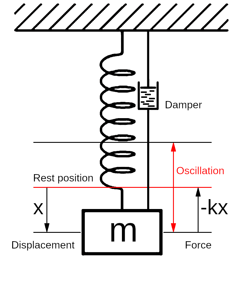
Mass suspended on a spring

Damping modes
Mechanical timekeepers depend on the phenomenon of resonance, the property of having a resonant or natural frequency at which a system vibrates. Resonant systems can be modelled by the concept of simple harmonic motion, the simplest example of which is a mass on a spring oscillating around its rest position, as shown in the figure.
In real systems, damping due to air resistance or friction causes the oscillations to die away and the mass comes to rest. These forces are represented by the dashpot damper in the figure. This is called a damped system or damped harmonic motion.
In a damped system where the energy losses are low, the oscillations die away slowly and the system is said to be under damped. If the system is heavily damped and energy losses are high, the mass does not oscillate at all, but returns slowly to the rest position, which is termed over damped. If the damping is such that the mass does not oscillate but returns to the rest position in the shortest possible time, that is, it only just fails to oscillate, the system is said to be critically damped.
The amount of damping present is quantified by the damping coefficient. The damping ratio ζ (zeta) is defined as the ratio of the actual damping coefficient to the critical damping coefficient. In a critically damped system, ζ is 1; in an over damped system it is greater than 1, and in an under damped system, less than 1.
The graph here shows the four damping regimes of undamped, under damped, critically damped and over damped simple harmonic motion. For under damped motion, the damped natural frequency \( \omega_d \) is lower than the undamped natural frequency \( \omega_n \), as shown by the slight lag of the red curve behind the blue curve.
The damped natural frequency for the under damped case 0 < 𝜁 < 1 is given by:
\[ \omega_d = \omega_n \sqrt{ 1 - \zeta^2 } \]What Q Measures
The Q factor works in the opposite direction to the damping ratio. In an over damped system, Q is low; in an under damped system, it is high.
Expressed mathematically, the Q factor is:
\[ Q = 2π \times \frac{energy \ stored}{energy \ lost \ per \ cycle} \]The Q factor is related to the damping ratio ζ by:
\[ Q = \frac{1}{2 \zeta} \]From this it can be seen that in a critically damped system when the damping ratio ζ is 1, Q = 0.5. In an under damped system when ζ is less than 1, Q is greater than 0.5, and in an over damped system when ζ is greater than 1, Q is less than 0.5.
The Q factor expresses how strongly, or how sharply, the system resonates. A low value for the damping ratio ζ and a large Q value means the system will oscillate for many cycles before stopping. A small Q value and high damping ratio means the system will oscillate for only a few cycles, or may not oscillate at all.
In real systems, the resonant frequency is always below the undamped natural frequency. The higher the Q and lower the damping ratio, the closer the resonant frequency approaches the undamped natural frequency. The sharpness of resonance indicates how closely the resonant frequency of a damped system approaches the undamped natural frequency; a higher Q corresponds to a closer approach and a narrower resonance peak.
Having described how the damping ratio ζ and the Q factor affect oscillation, it appears that ζ is an adequate quantification and Q is rather unnecessary, so is natural to ask how and why the symbol Q originated.
The Origin of Q
The concept of damped harmonic motion and the damping ratio existed a long time before Q, so where did Q come from?
The Q factor was defined in the early 1920s by the American engineer Kenneth Simonds Johnson when analysing filter circuits based on capacitors and inductors for telephone systems. One of the parameters Johnson used was the coil dissipation constant \(d\), the ratio of resistance to reactance in a coil or inductor, defined by \( d = R / L \omega \) where R is the resistance, L is the inductance in Henries and \(\omega\) is the angular frequency in radians/second, equal to \( 2 \pi f \), where f is the frequency in hertz.
The coil dissipation constant in a resonant circuit is small, and becomes smaller as the resonance becomes stronger. To make the value of the constant easier to write, Johnson defined Q for an inductor at its resonant frequency as the inverse of the coil dissipation constant. This meant that a coil dissipation constant of 0.004 could be more simply written as a Q value of 250. Of course, 0.004 can also easily be written in engineering notation as 4e-3 or \( 4 \times 10^{-3} \).
Johnson is thought to have chosen the letter Q for the inverse of the coil dissipation constant simply because other letters had already been assigned to other parameters; the concept of ‘quality’ did not come into it.
Although Johnson’s Q has nothing to do with quality, later writers, perhaps perhaps because the word ‘quality’ begins with Q, mistakenly assumed it did, and the term ‘quality factor’ became entrenched. However, this is misleading because Q is a purely quantitative characteristic.
Knowing what Q really quantifies, it is worth looking at its relationship to quality.
The Q Factor and Quality

A skip hanging from a tower crane has a high Q
The following examples illustrate how the Q factor relates to the quality of some systems.
- A skip hanging from a tower crane has very low damping and high Q. If the crane operator moves the jib quickly and stops it suddenly, the skip will continue swinging in a wide arc for a long time. This is a dangerous situation, and crane operators are trained to avoid it. Does the high Q mean that this a high quality system? No, of course it doesn't.
- The suspension of a motor car is heavily damped to prevent oscillations that make passengers feel sick. The suspension of, say, a Rolls Royce motorcar therefore has a low Q. Does this mean that a Rolls Royce motorcar is a low quality system? Definitely not.
- Speakers and microphones are designed to avoid high-Q resonances that would create sharp peaks at specific frequencies. Instead, they aim for a flat frequency response with equal amplification across all audible frequencies. A high-Q resonance would make some notes much louder than others, creating unnatural reproduction, which would be very Lo-Fi instead of Hi-Fi. Does this mean that high quality audio equipment that suppresses high-Q resonances through careful design is actually low quality? Of course not.
The lesson of these examples is that a high Q value is not always desirable. In the case of the tower crane, the high Q value is dangerous, and tower crane manufacturers would pay highly for an invention that reduced Q to 0.5. In the case of the Rolls Royce motor car, the suspension system is designed to have a low Q so that the car's occupants feel they are gliding along rather than bouncing up and down.
The right level of Q, like the damping ratio, depends on the purpose of the system. Sometimes a high Q is desirable; sometimes a low Q is more appropriate.
The Q factor is not a measure of ‘quality’, which is not a quantifiable concept. Q does not measure craftsmanship, materials quality, precision of manufacture, reliability, or any of the other things meant by ‘quality.’ A long-case pendulum clock with a cheap, mass-produced, movement has a much higher Q than the finest marine chronometer ever made. But which is the higher quality?
It is unhelpful to call Q the quality factor, because that conveys no meaning about what is being measured, and suggests that a system with high Q is in some way high quality, which, as the examples show, is not true. If the Q factor must have a name based on the letter q, it would be more helpful to call it the quizzle factor, rather than the more loaded and prejudicial quality factor.
However, a much better term for Q would be ‘resonance factor’. Resonance and damping are closely related concepts. Heavily damped systems with a high damping ratio have a low Q, whereas lightly damped systems have a high Q. The Q factor is inversely related to the damping ratio ζ (zeta) in the same way that a resonant system is inversely related to a damped system.
Q is a perfectly valid concept — but remember, it has nothing whatsoever to do with quality.
The Q Factor and Watches
In mechanical systems, the Q factor is a quantification of how much energy is lost by a resonant system such as a watch balance or a clock pendulum during each cycle, compared to the amount of energy stored in the resonator. A low Q factor means that a large proportion of energy is lost per cycle, and a high Q factor means that a small proportion of the stored energy is lost per cycle. A higher Q factor is desirable in a resonant system, because it means that less energy needs to be added during each cycle to replace that which is lost.
In a mechanical watch, energy is stored in the balance and spring, as kinetic energy in the motion of the balance and potential energy in the coiled spring. As the balance swings, energy moves backwards and forwards between the spring and the balance. Some of this energy is lost during each cycle due to friction at the pivots and air resistance. The lost energy has to be replaced to keep the balance swinging.
Although it is intuitive that the amount of friction should be minimised in a high quality system, there is also a technical reason for reducing the amount of energy lost per cycle in a watch. The lost energy is replaced by the impulse given to the balance during the action of escaping. The impulse disturbs the balance, which is detrimental to timekeeping. A smaller impulse disturbs the balance less than a larger impulse, so is better for timekeeping. It also means that the total power consumed by the watch is lower, and a smaller mainspring exerting less torque can be used.
Reducing friction is always a good principle, because it reduces wear and the driving force needed. Coincidentally, it also increases Q. However, increasing Q by increasing the moment of inertia of the balance, by increasing its radius and the mass of its rim, has drawbacks as well as benefits. A more massive balance is subject to greater gyroscopic forces when a watch, particularly a wristwatch, is moved. The inertia of a watch balance must be high enough to store adequate energy relative to losses, but low enough to avoid disturbing gyroscopic effects.
However, because of the small size of watches, the Q value of a watch’s regulating system, the balance and spring, is never large, usually measuring in the hundreds rather than thousands. Typical Q values are:
- A mechanical watch with a sprung balance: 200–300
- A marine chronometer with a larger balance: 500–1,000
- A long-case pendulum clock: several thousand
Is a High Q Factor Better?
Although small clocks suffer from the same constraints as watches, pendulum clocks, especially long-case clocks, inherently have much higher Q values. The Q value of a simple long-case clock is in the thousands, and can easily be made much higher by increasing the mass of the pendulum.
There is a well-known graph by Douglas Bateman that plots timekeeping accuracy against Q values. This shows a strong correlation between increasing Q value and accuracy. From this, it appears that to increase the accuracy of a clock, all that is needed is to increase the Q value of its oscillator.
However, a problem with increasing Q values to very high levels is that a clock with a massive pendulum takes a long time to recover from an external shock. Followers of John Harrison's work argue that a lower Q value is better if it is accompanied by natural error-correcting characteristics built into the design of the clock, so that it can quickly recover from external shocks. The performance of Martin Burgess's clocks lends weight to this argument.
The argument has been debated for many years, but it appears that both methods are valid ways of producing very accurate clocks.
Conclusion
The Q factor does not measure craftsmanship, materials quality, precision of manufacture, reliability, or any of the other things meant by ‘quality.’ It is worth remembering this when showing off your latest horological creation with a high Q value. If you say it has a high Q value and is, therefore, high quality, someone might ask ‘Does that mean high quality like a skip full of scrap iron hanging from a crane?’
Like the damping ratio, Q is a parameter of a system. A better term for the Q factor would be ‘resonance factor’.
If you have any comments or questions, please don't hesitate to get in touch via my Contact Me page.
Copyright © David Boettcher 2005 - 2026 all rights reserved. This page updated November 2025.
Back to the top of the page.